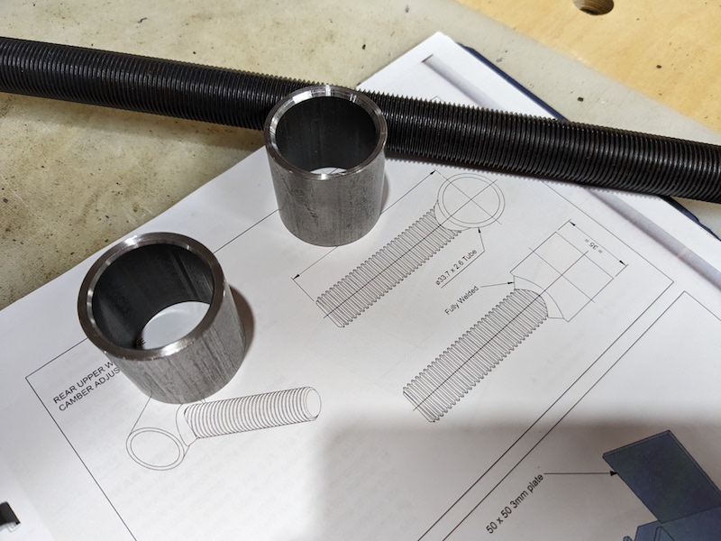
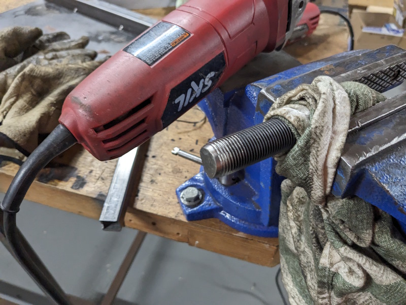
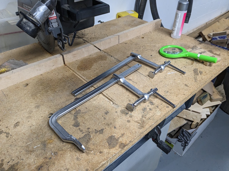
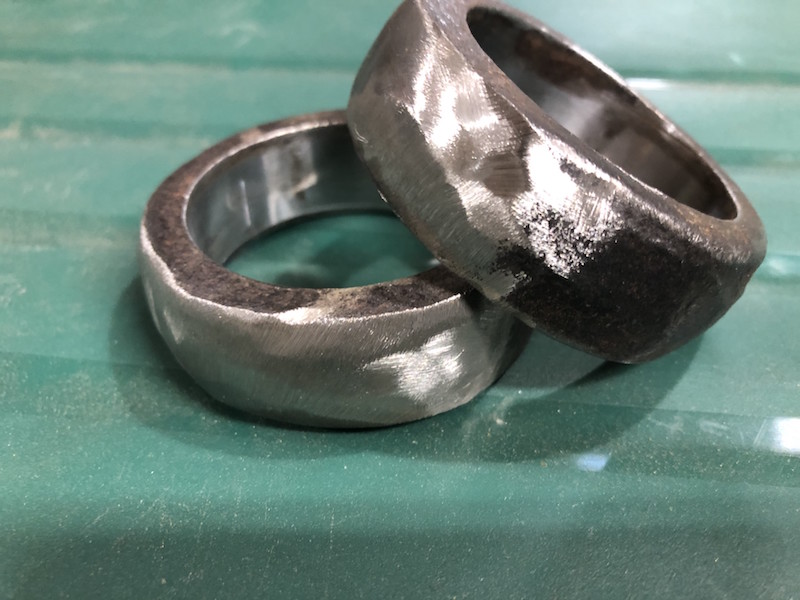
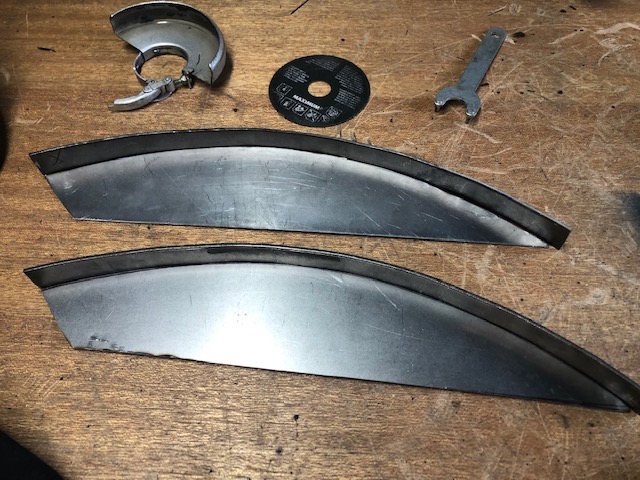
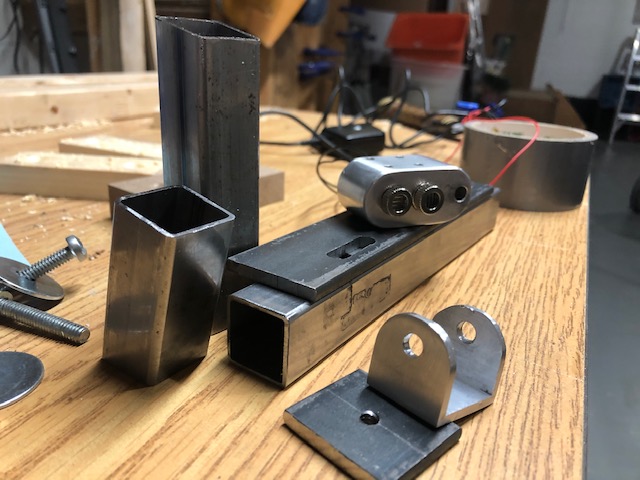
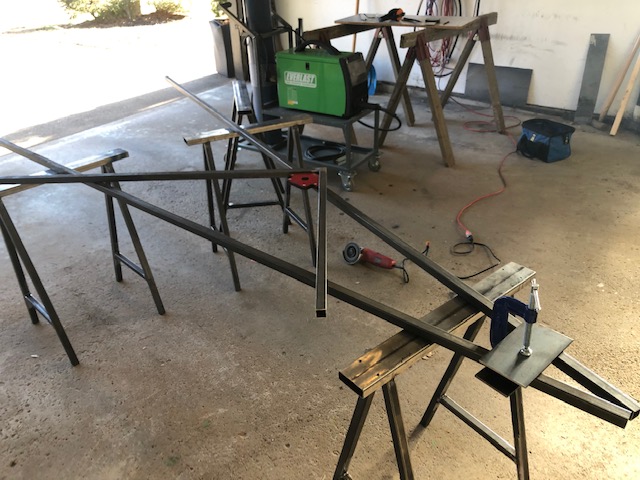
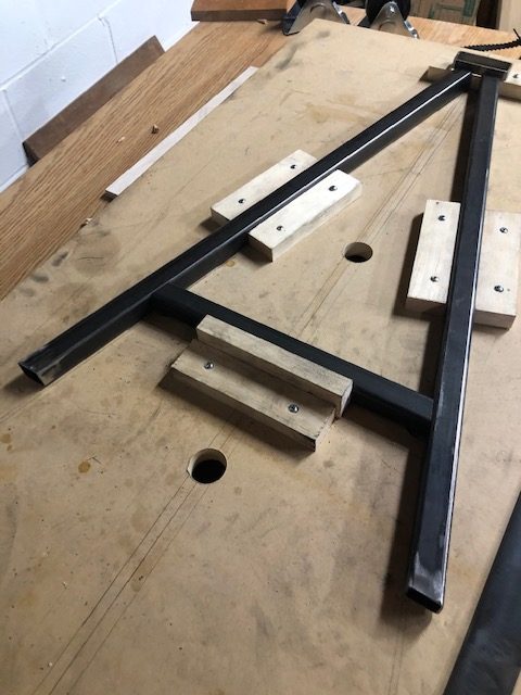
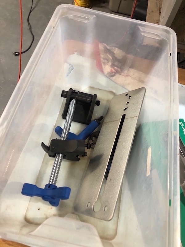
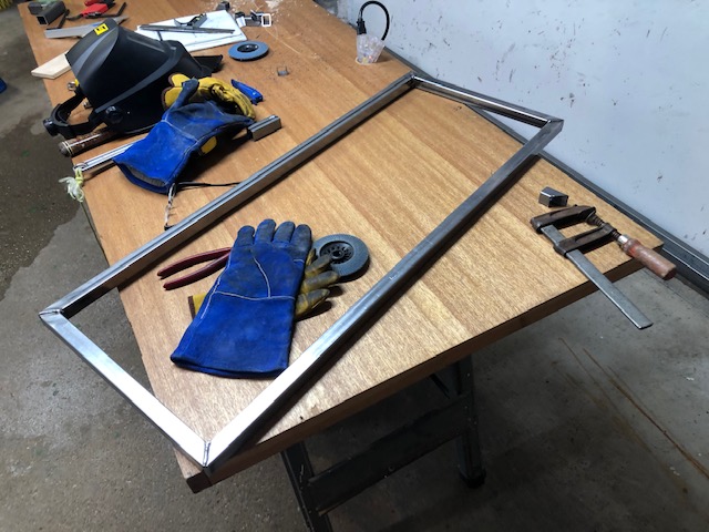
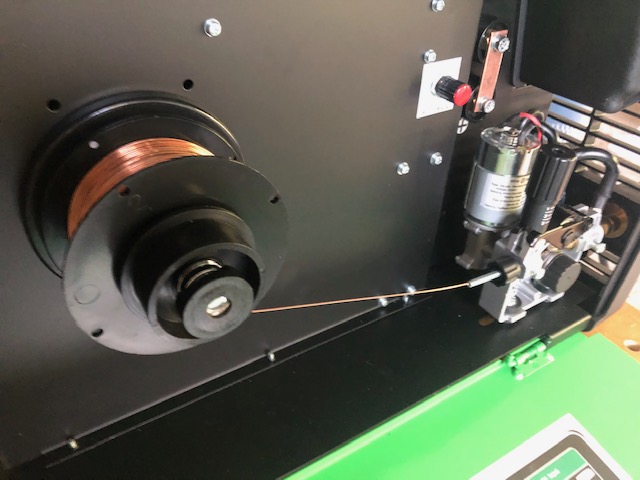
Time to fabricate the camber adjusters for the rear suspension – twice.
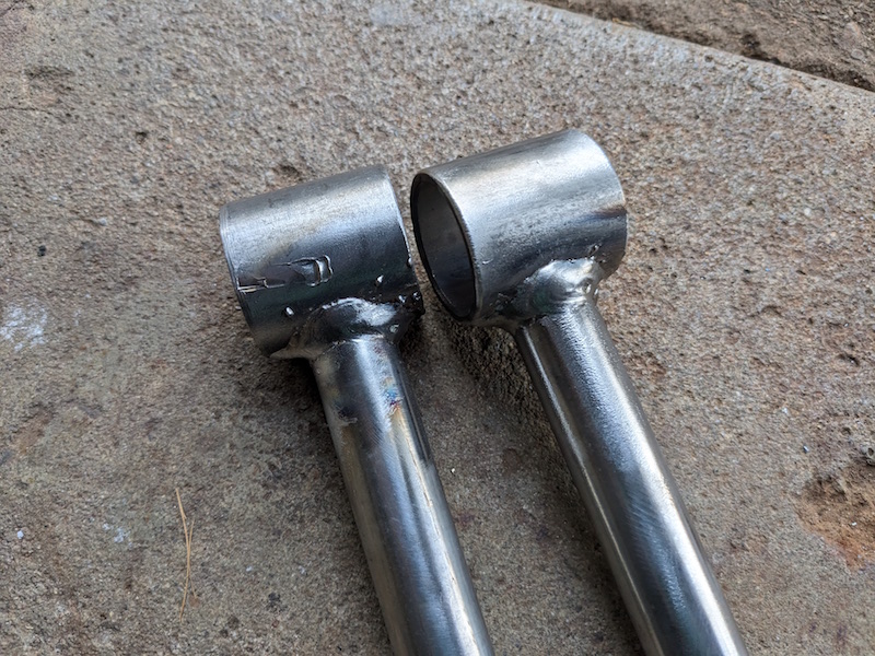
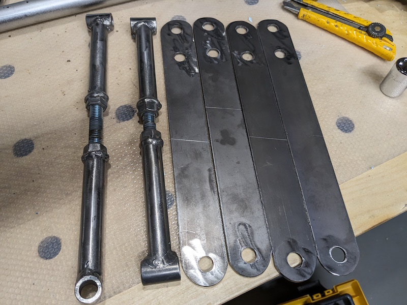
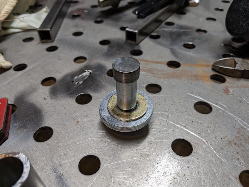
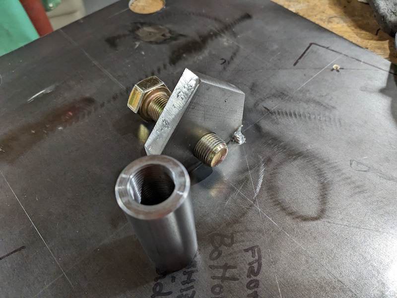
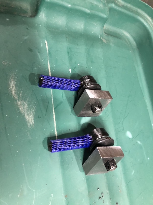
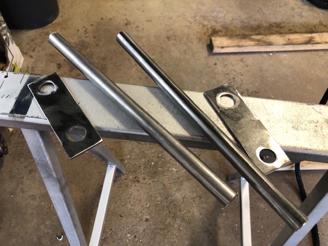
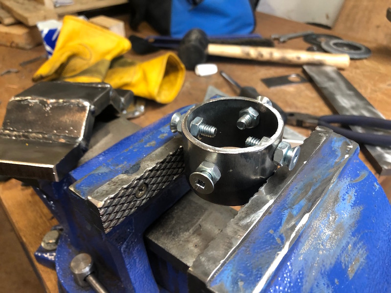
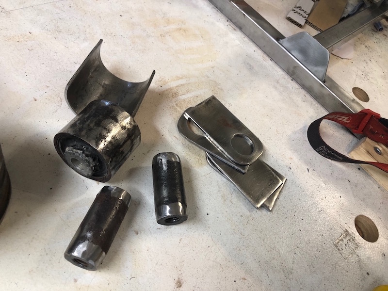
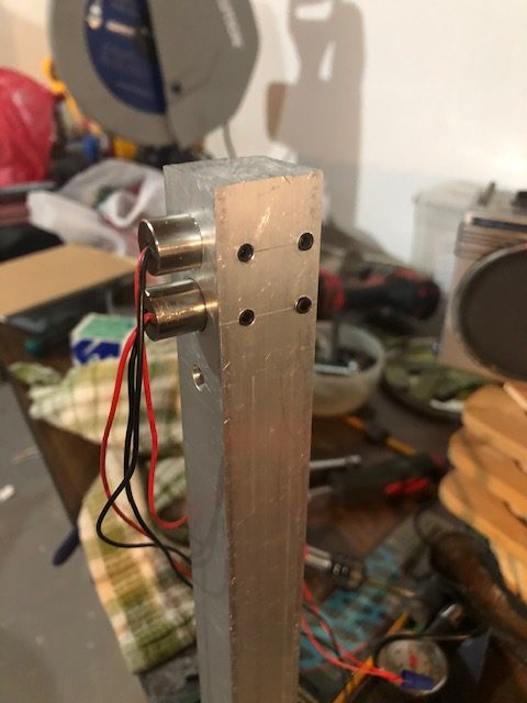
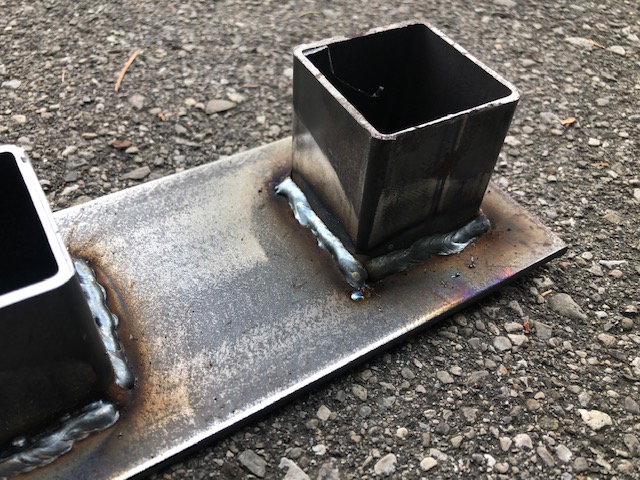
These connectors attach the top control arm to the yet to be fabricated rear hubs. once they are fabricated, the rear suspension components can be assembled and used to help determine what the hubs will look like. A short length of high strength threaded rod needs to be welded onto a bushing tube.
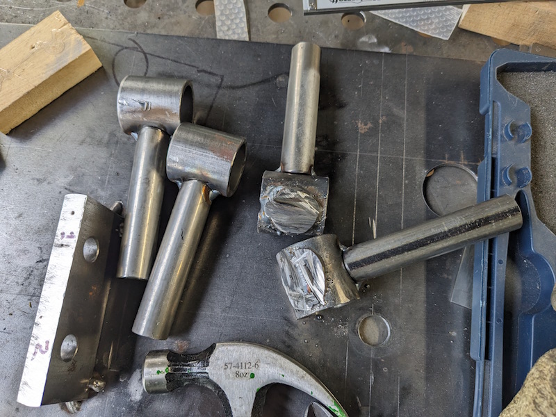
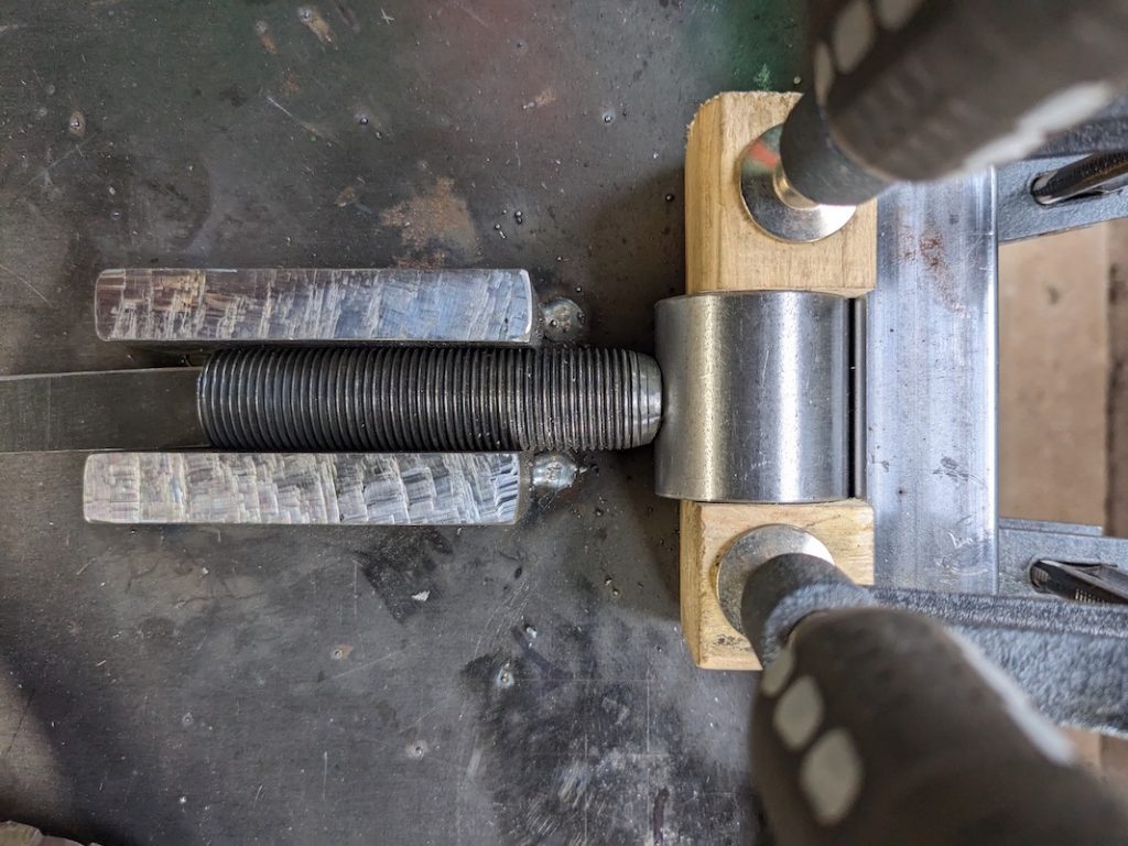
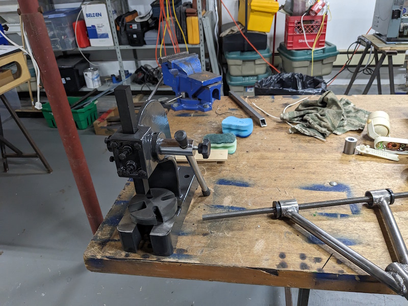
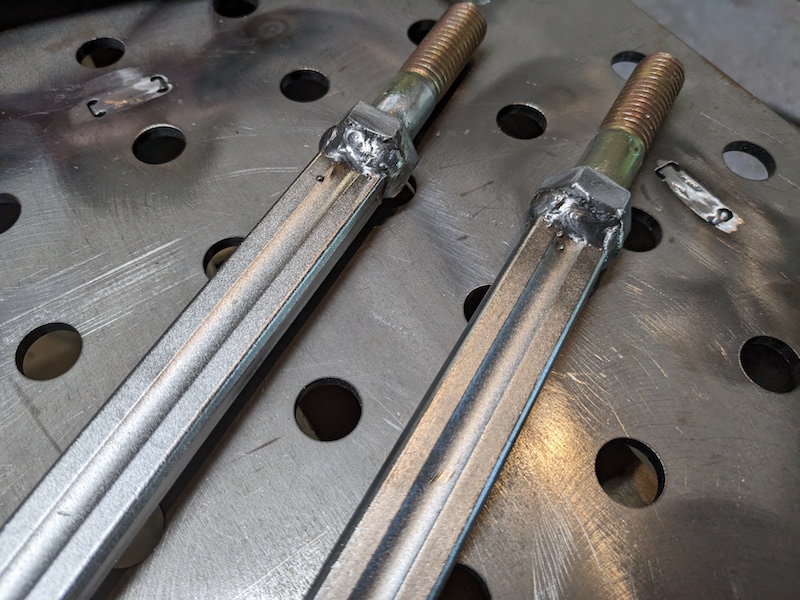
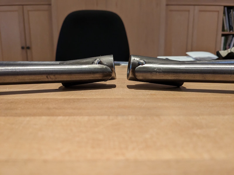
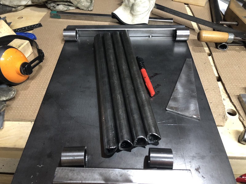
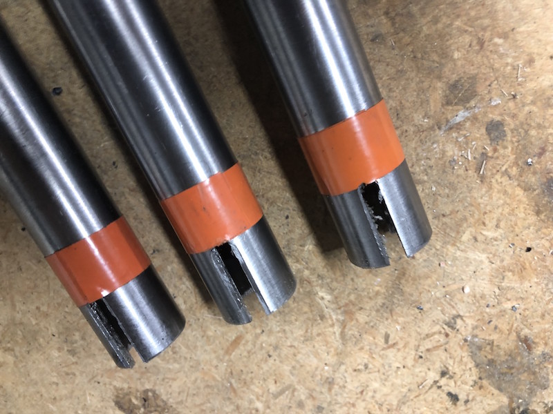
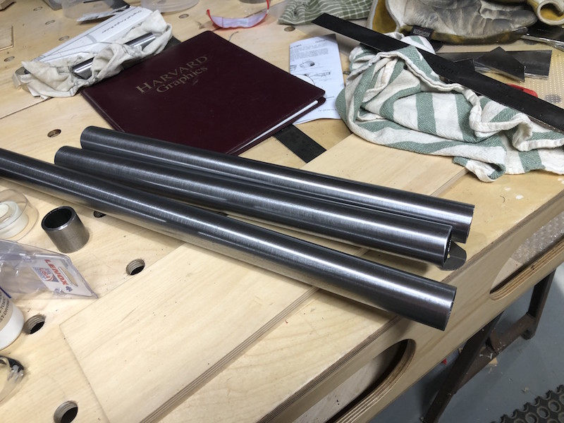
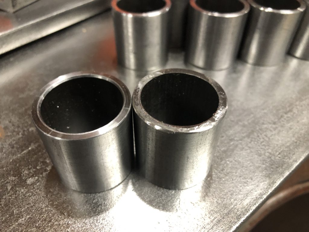
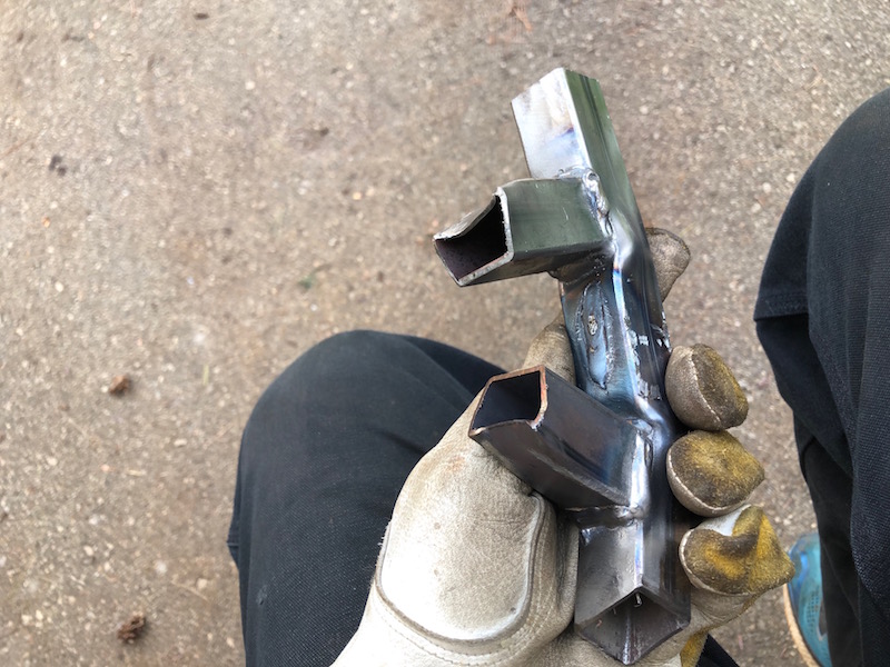
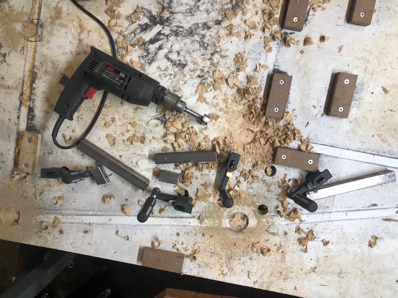
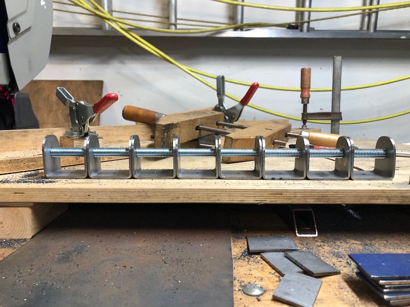
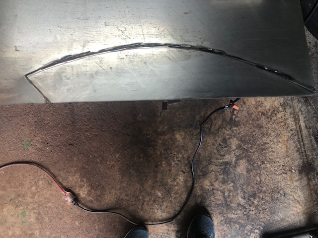
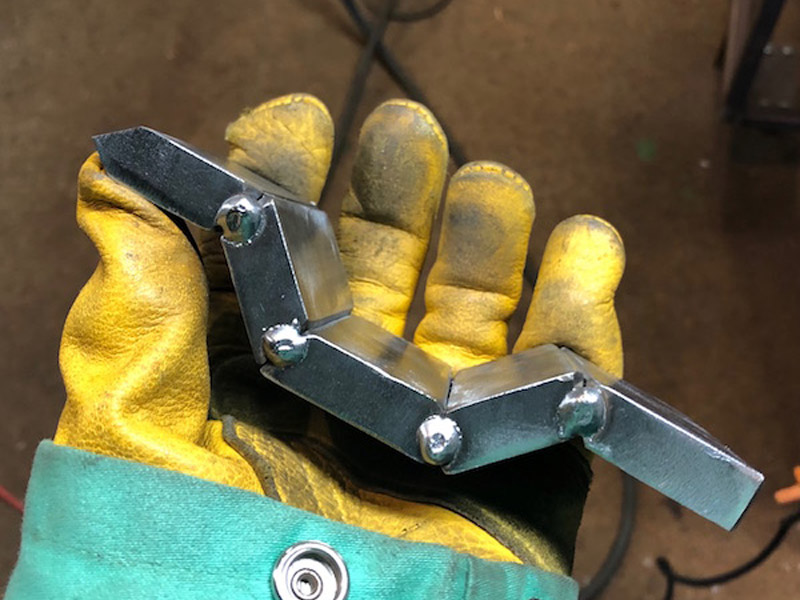
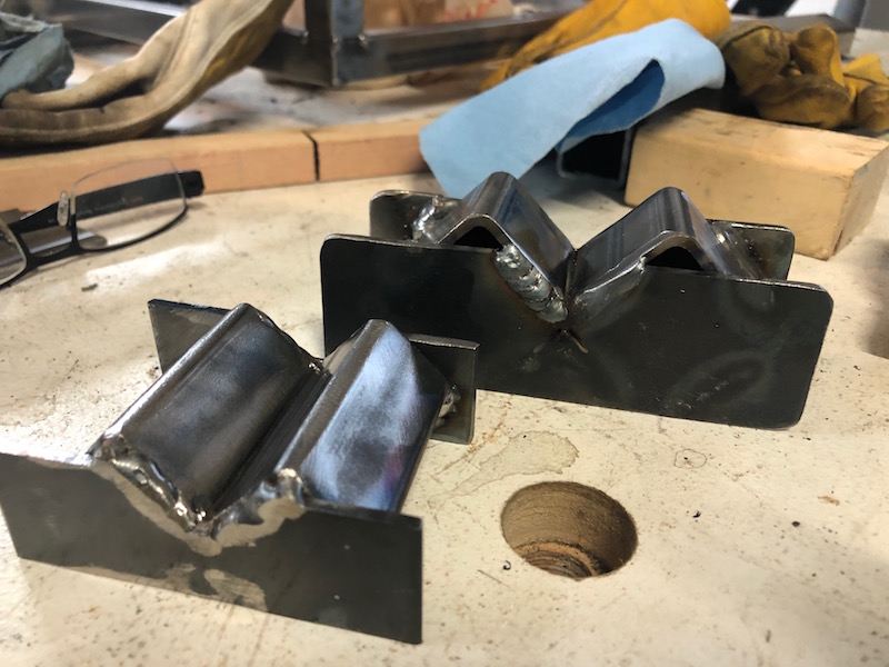
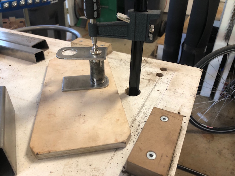
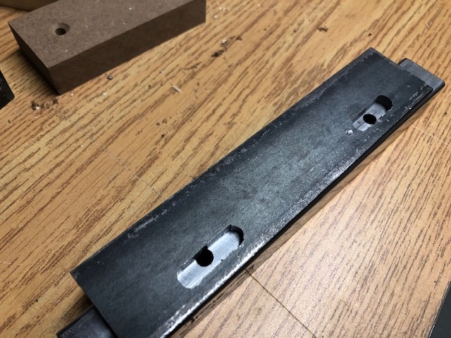
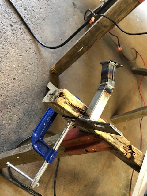
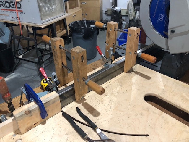
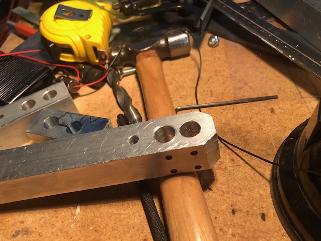
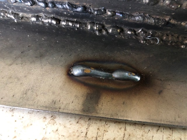
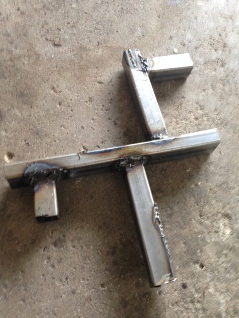
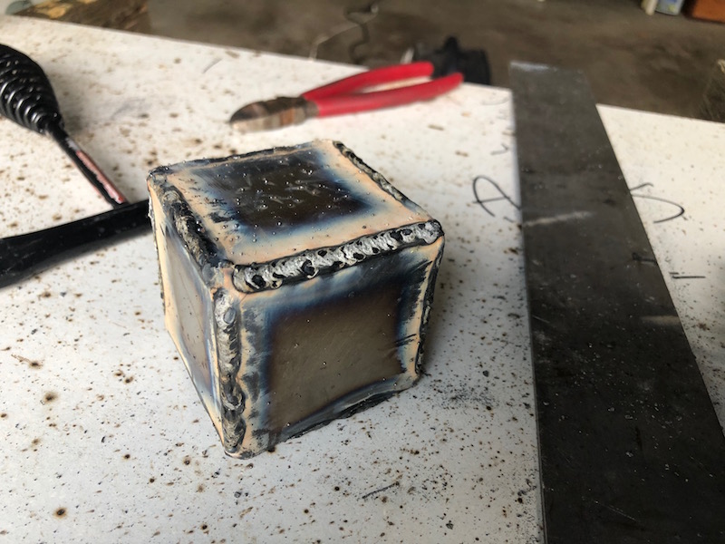
My first attempt did not go well, welds were messy and alignment was not good. I needed some practice so I made up practice pieces using scrap 3/4″ tubing rather than threaded rod. I tacked them together ready for welding. The two on the right are made with the bushing tubes salvaged from the first attempt!
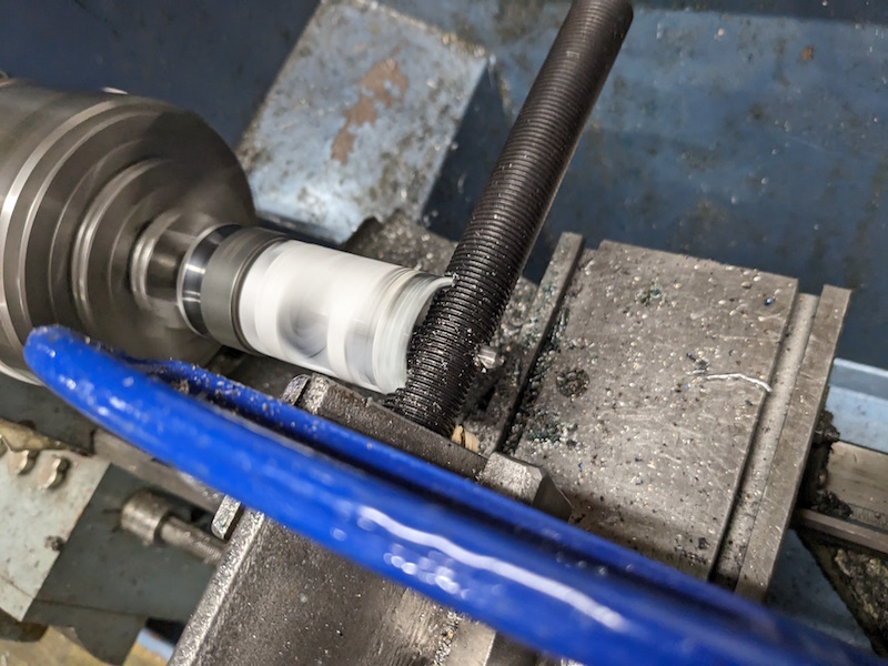
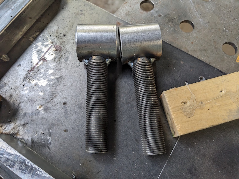
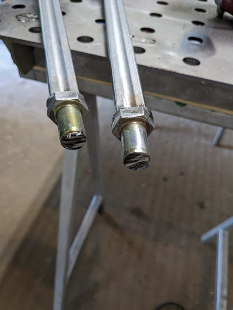
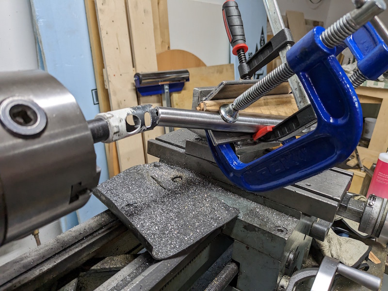
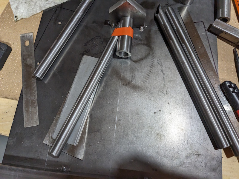
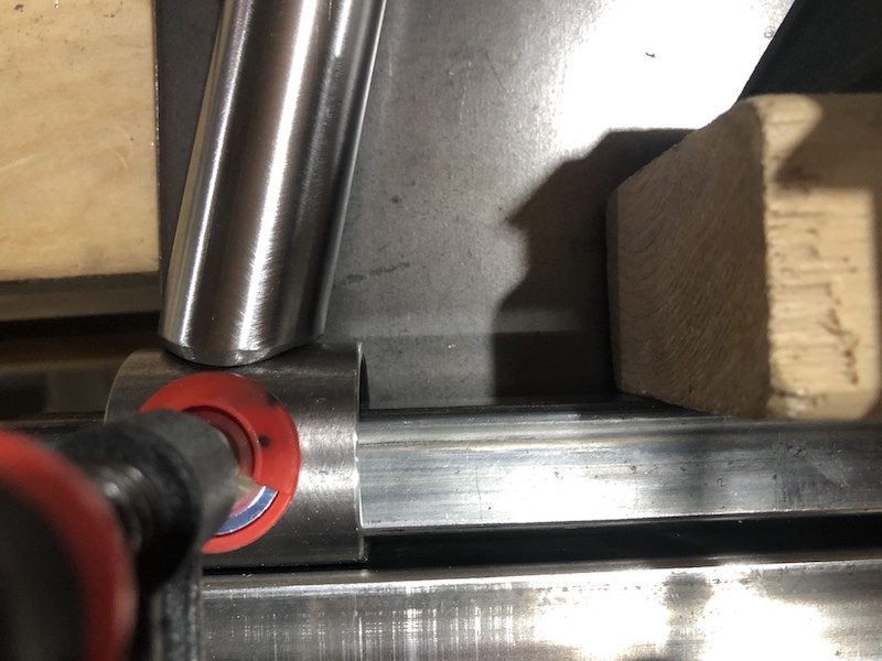
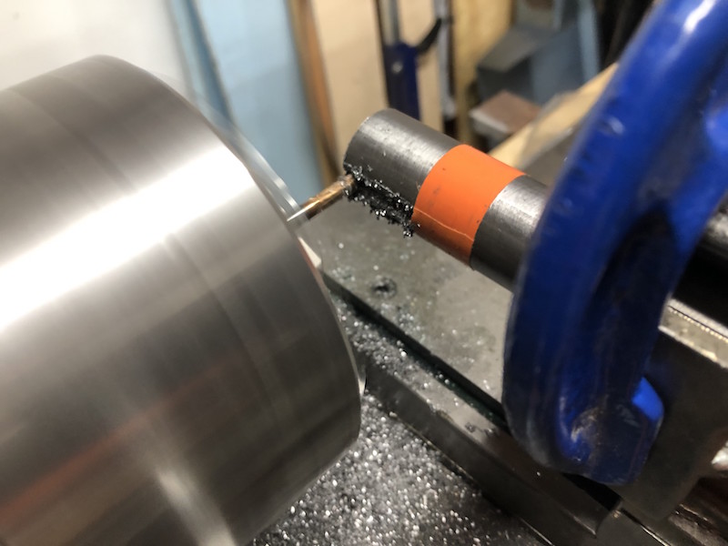
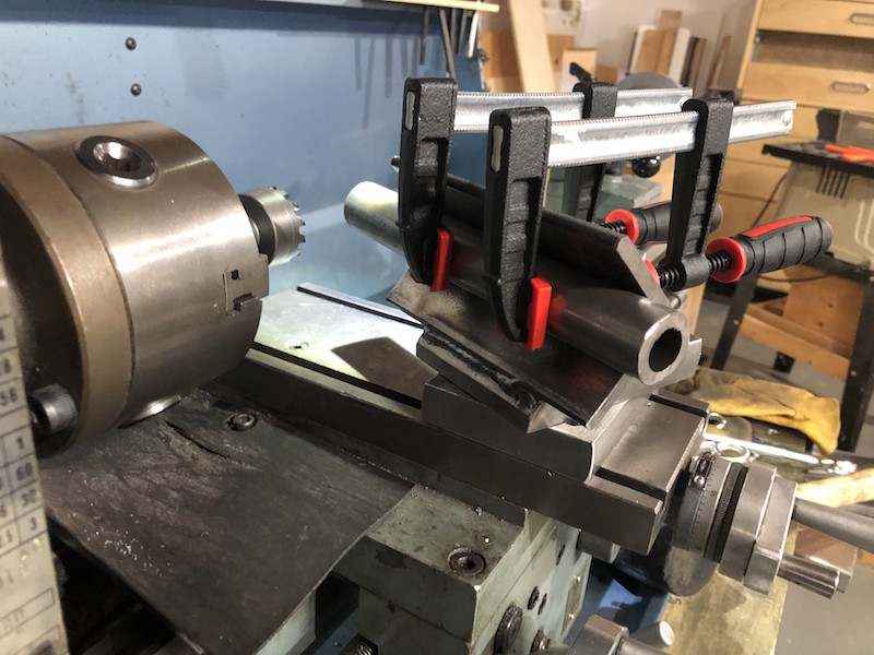
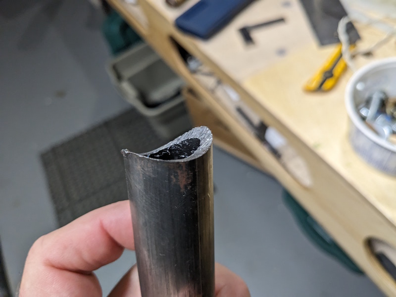
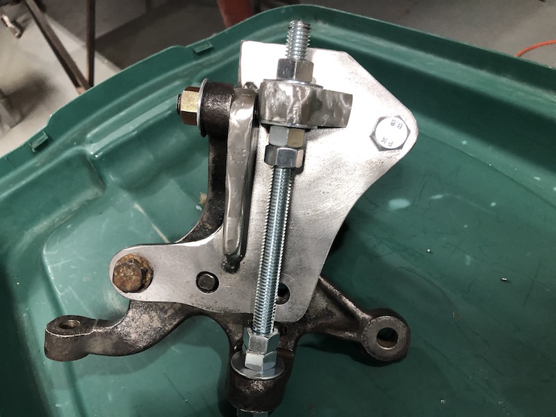
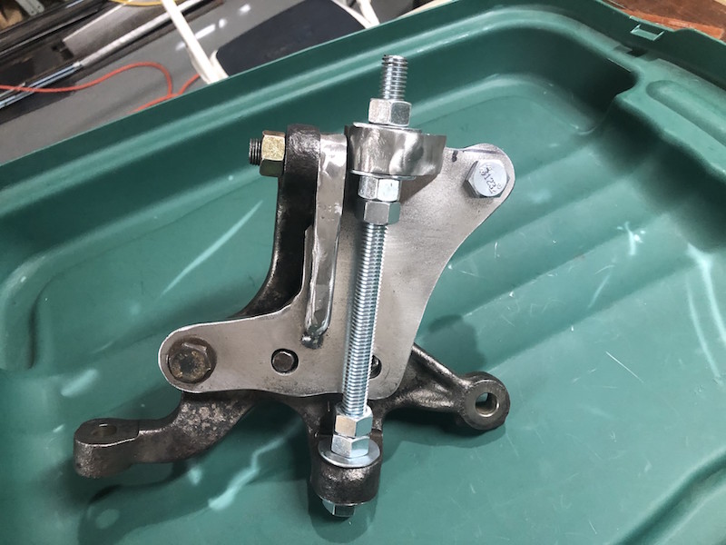
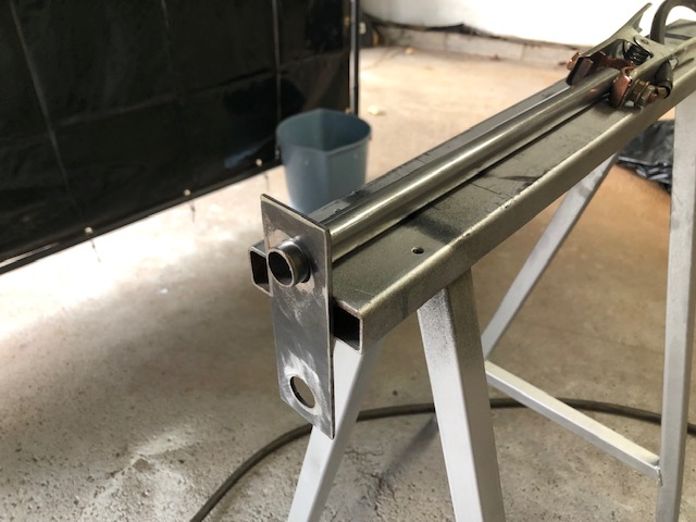
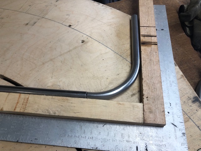
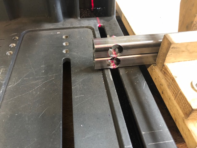
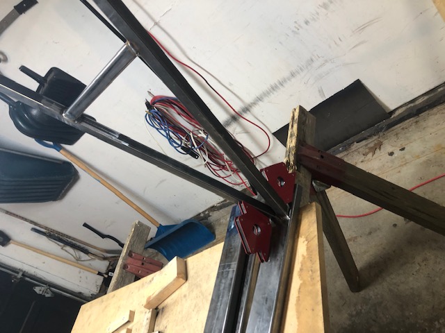
The lathe is instrumental once again! The weld area is tapered and everything is aligned in the jig for tack welding.
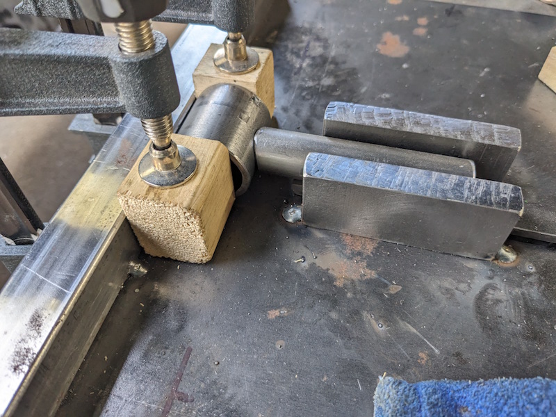
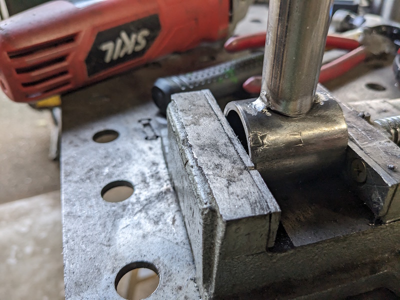
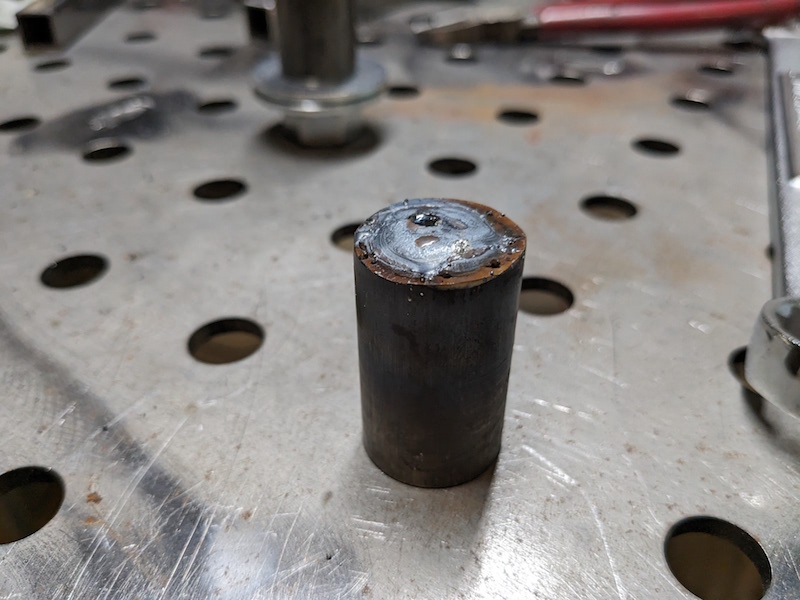
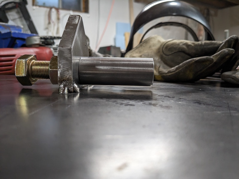
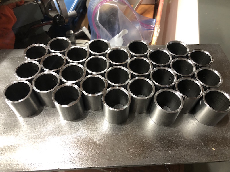
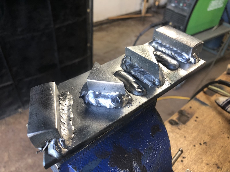
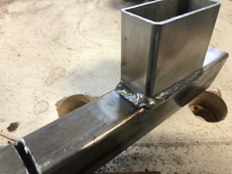
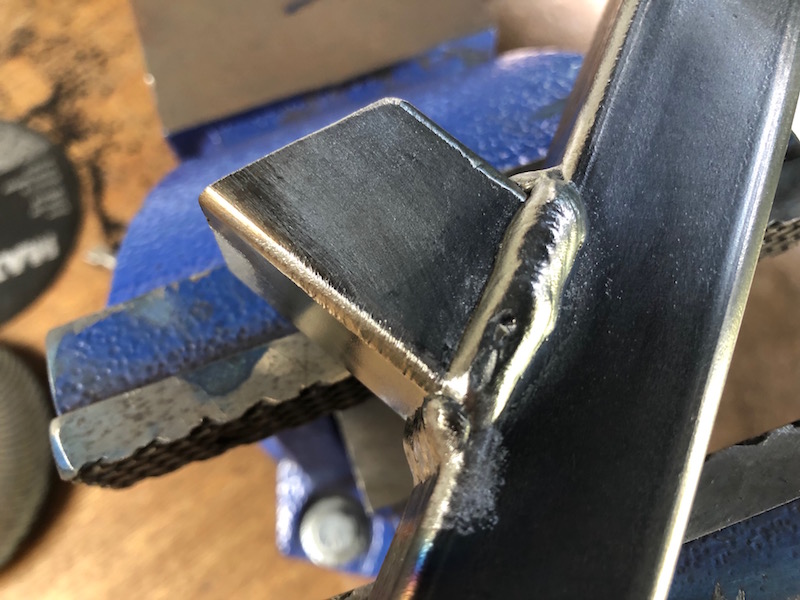
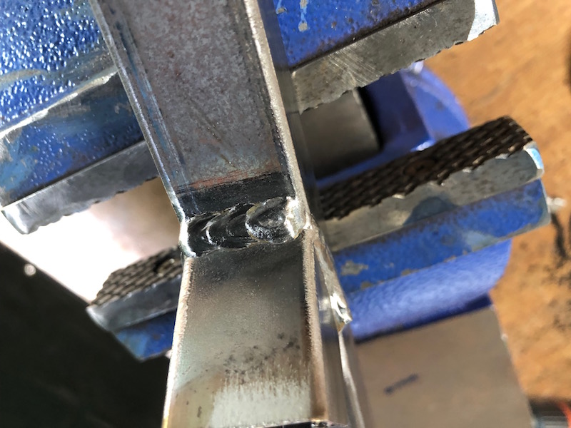
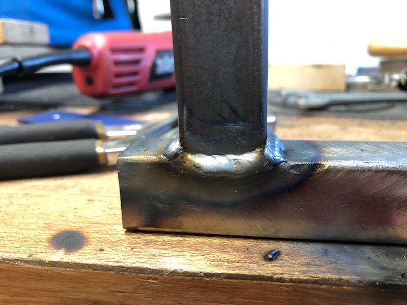
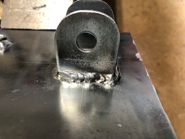
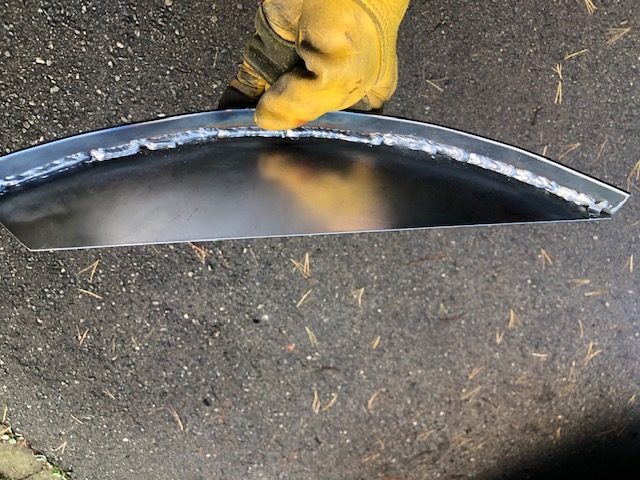
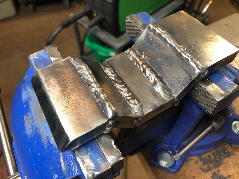
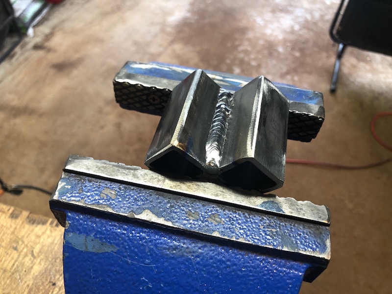
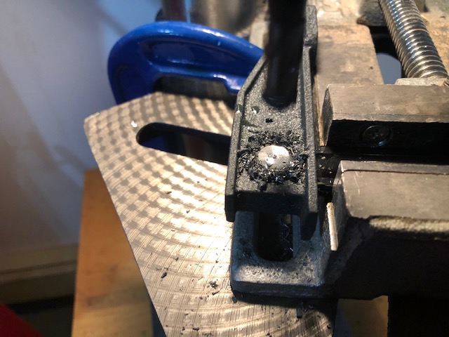
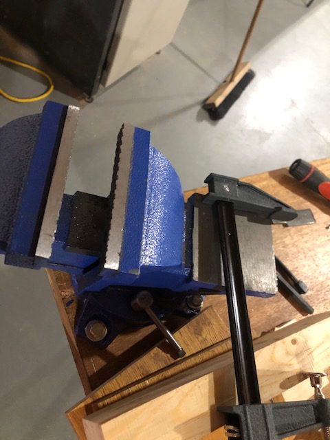
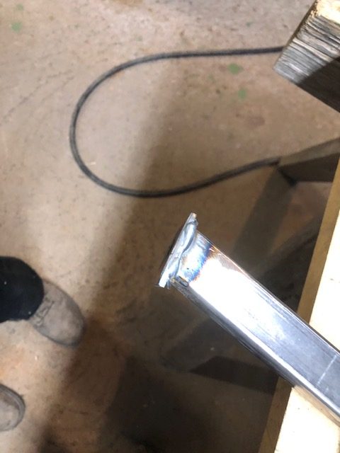
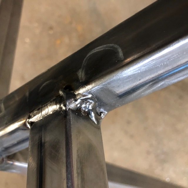
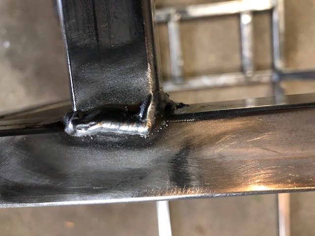
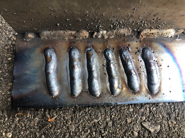
In order to fully weld the practice pieces I clamped them upright in a small vice. In this orientation I could weld half way around the tube without interruption. I set the welder heat higher than the metal thickness recommendations and the results were very good. Time to move on to the camber adjusters.
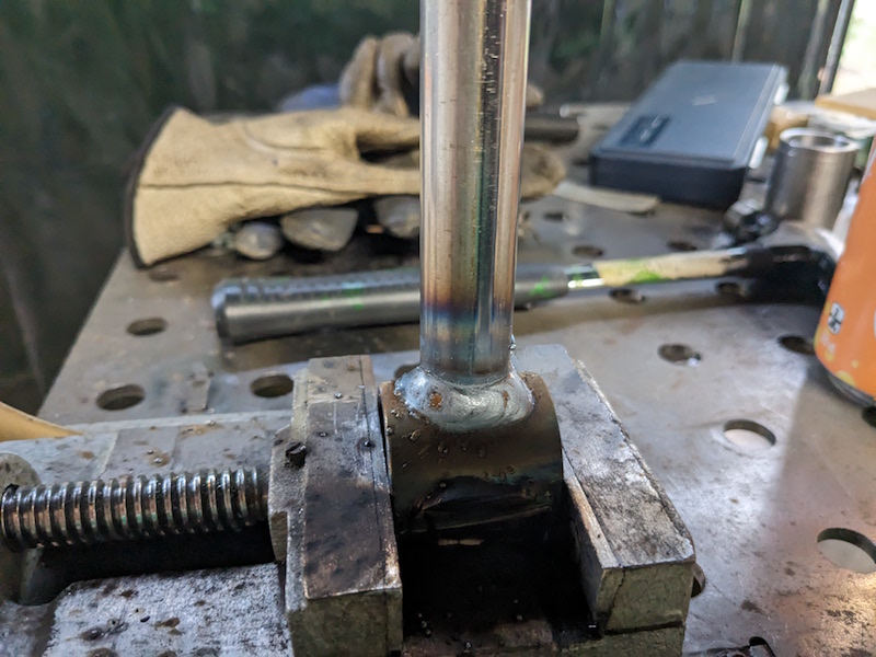
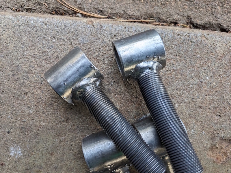
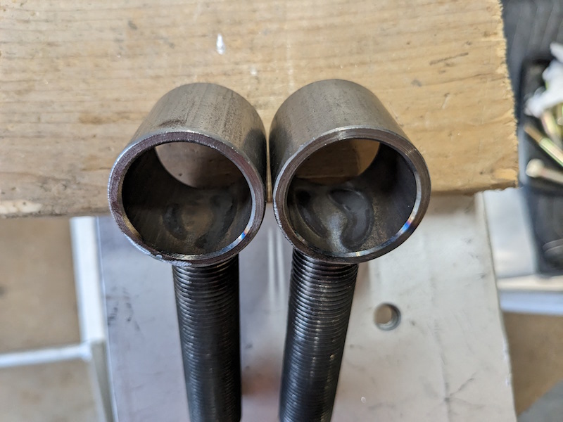
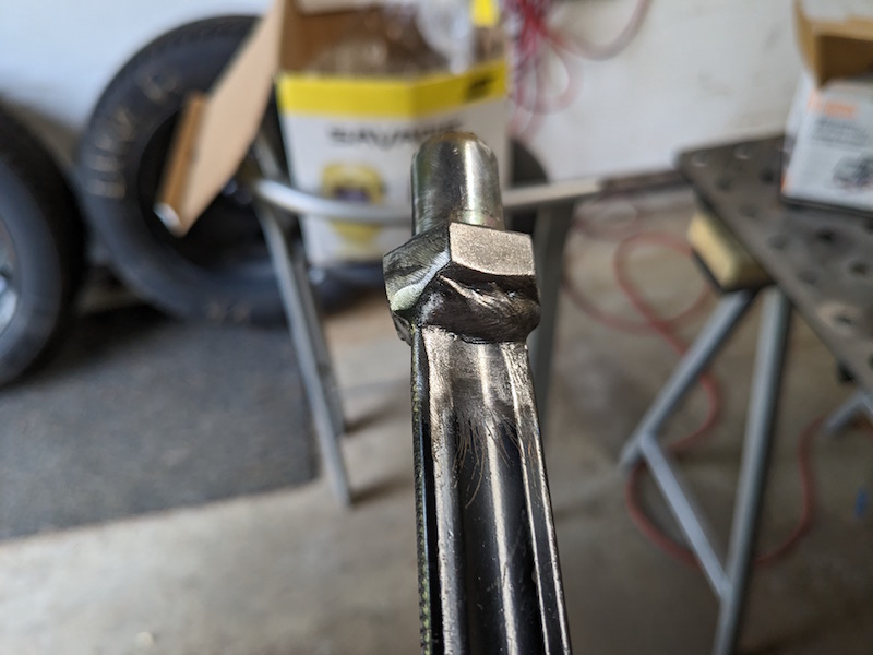
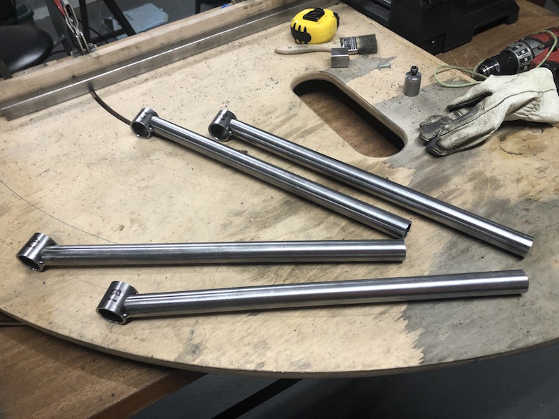
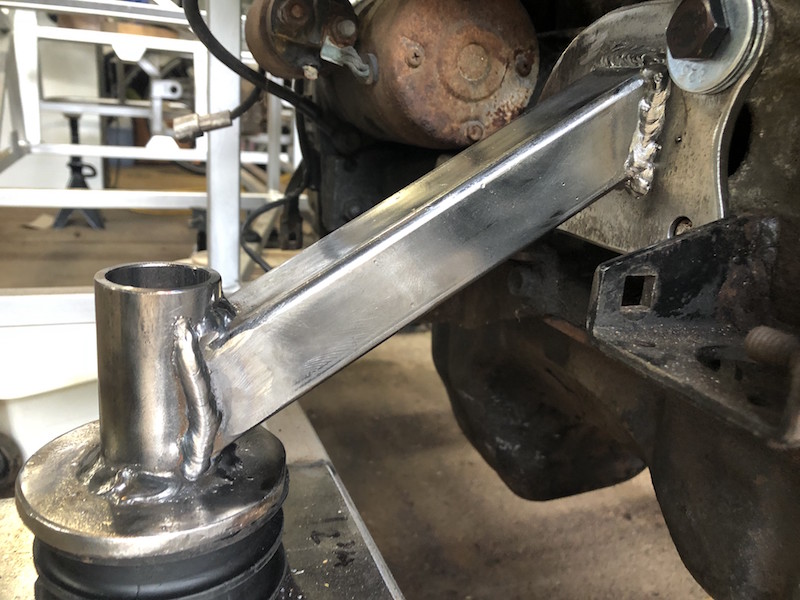
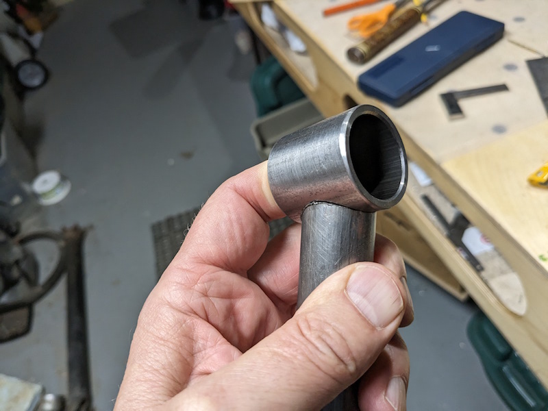
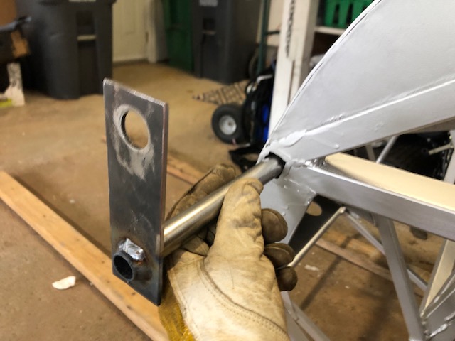
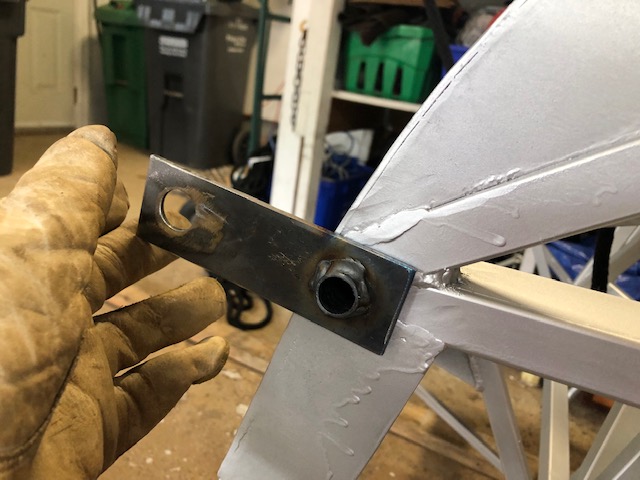
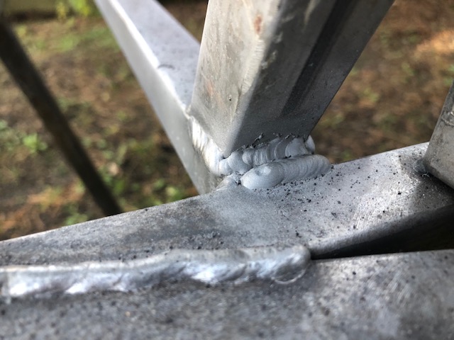
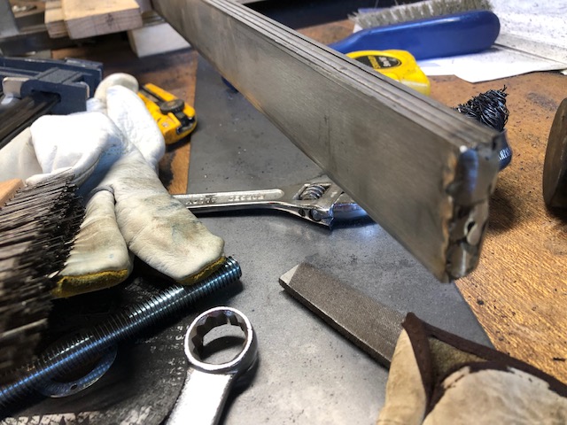
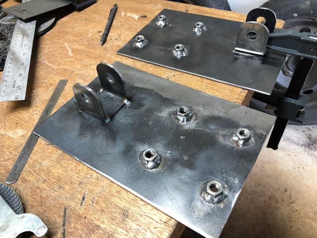
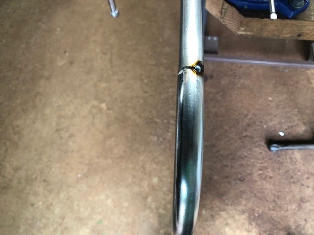
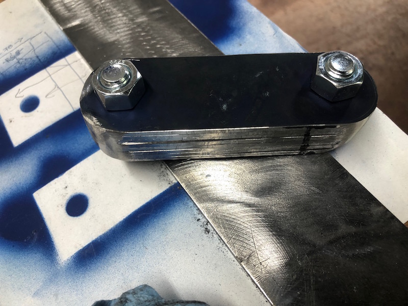
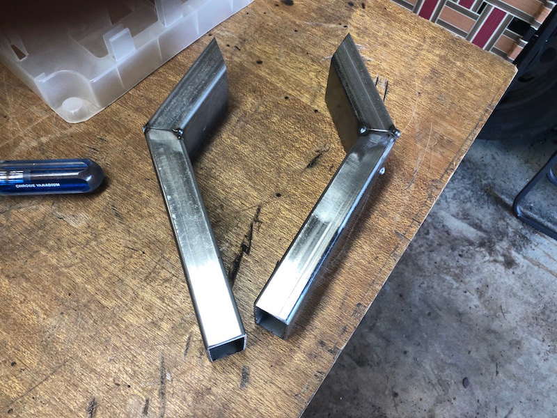
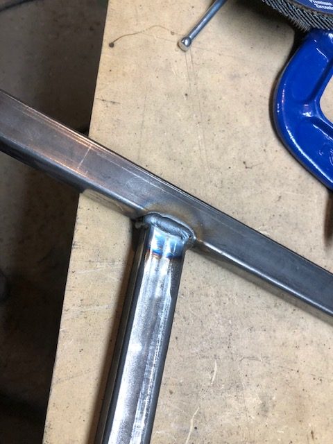
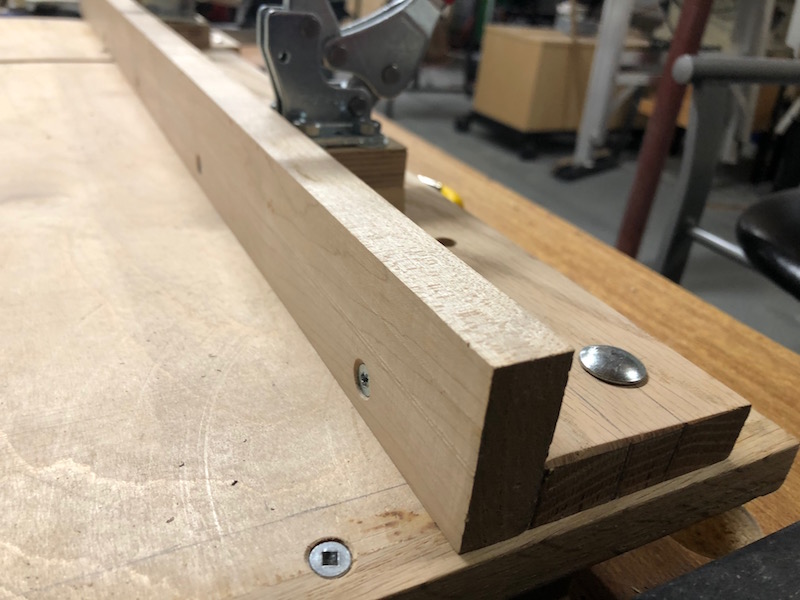
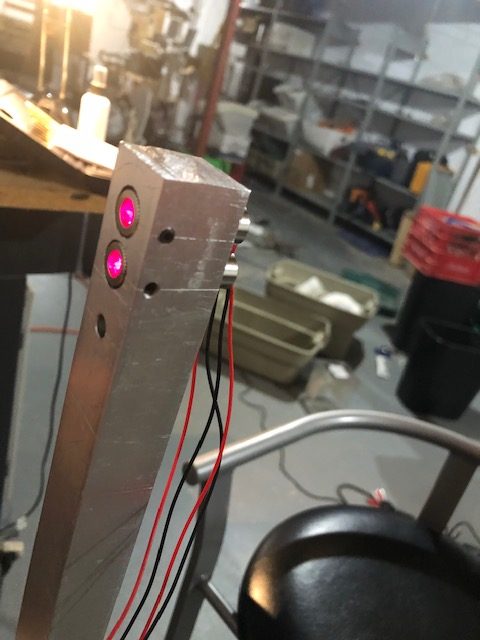
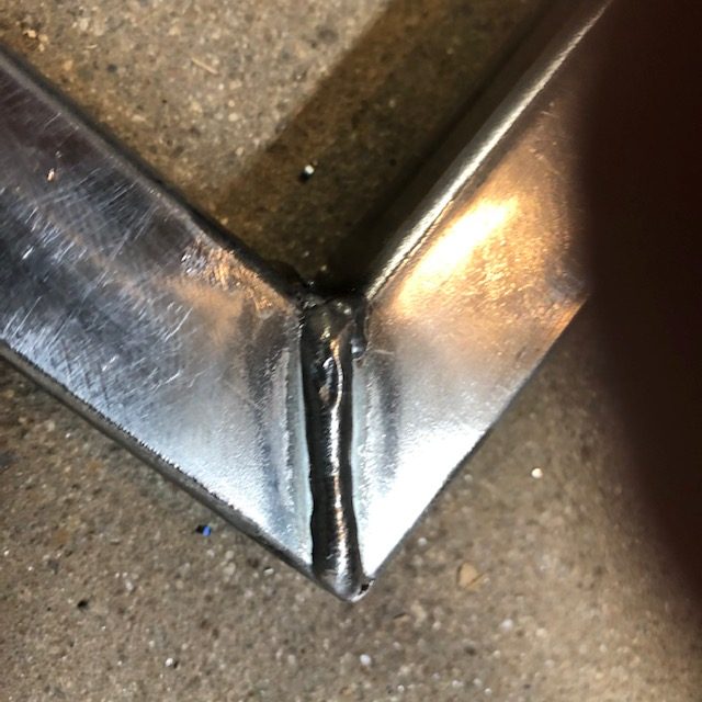
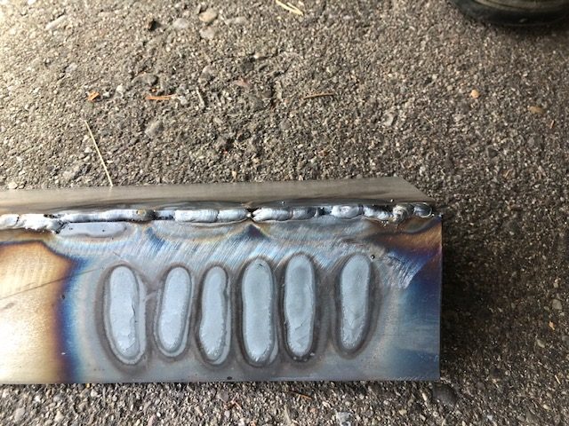
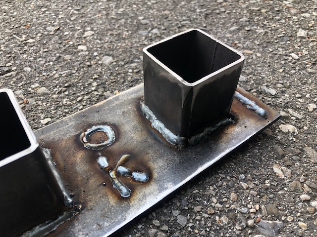
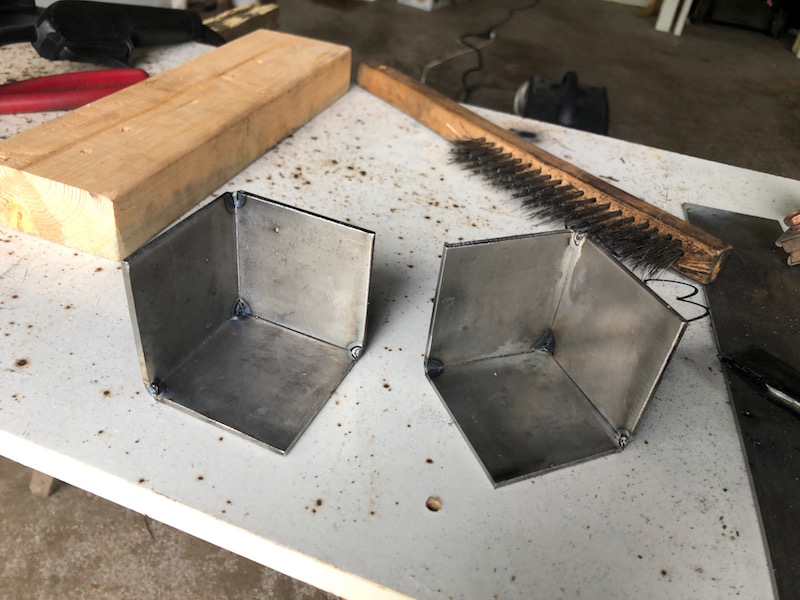
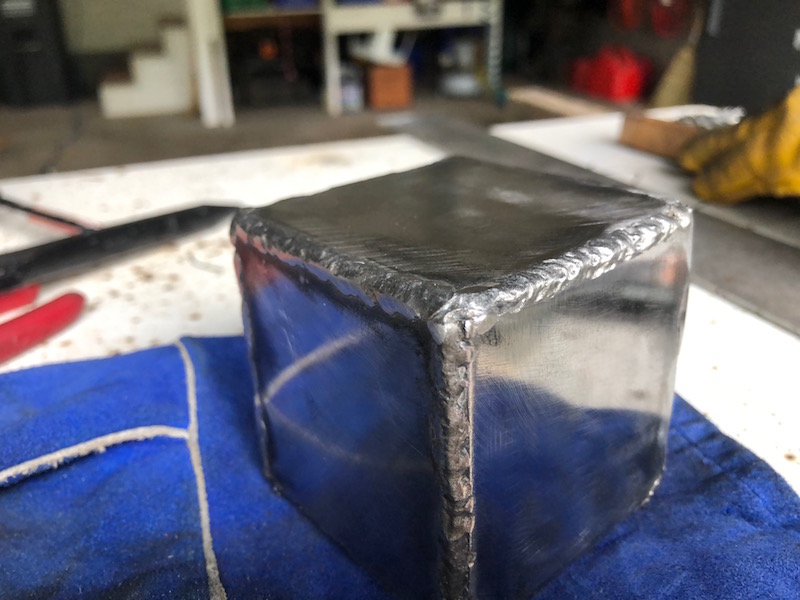
Tacked and fully welded. I’m very happy with these welds, you can see the heat marks left on the inside of the bushing tubes.
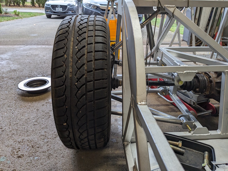
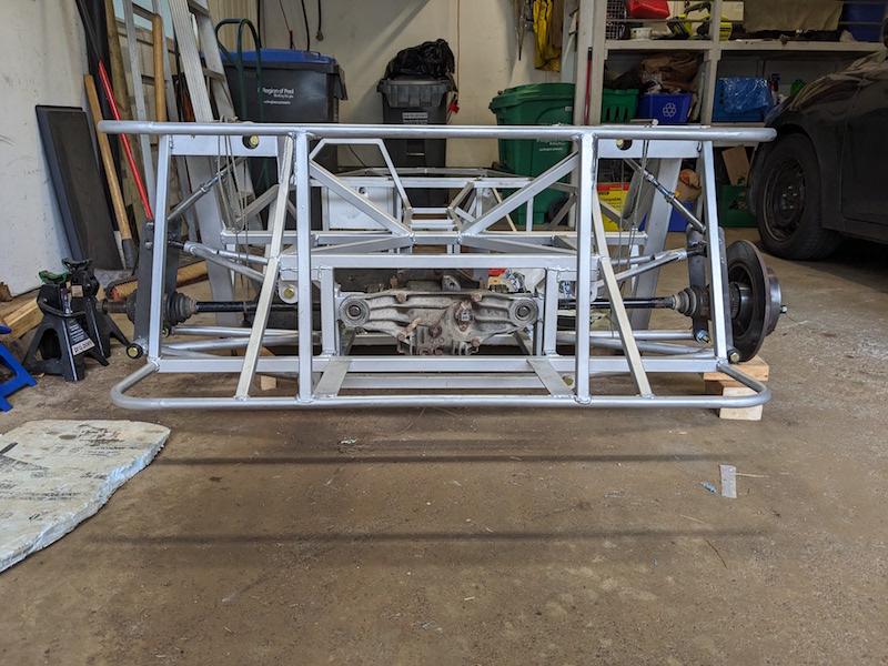
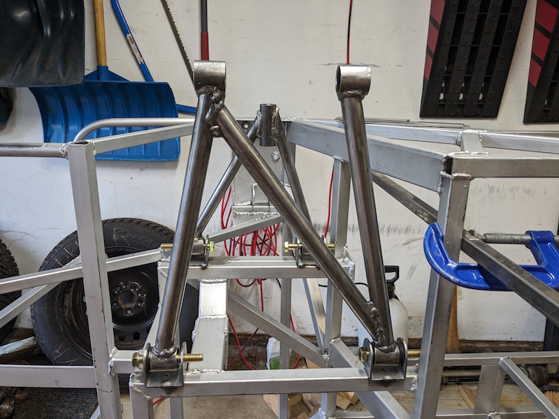
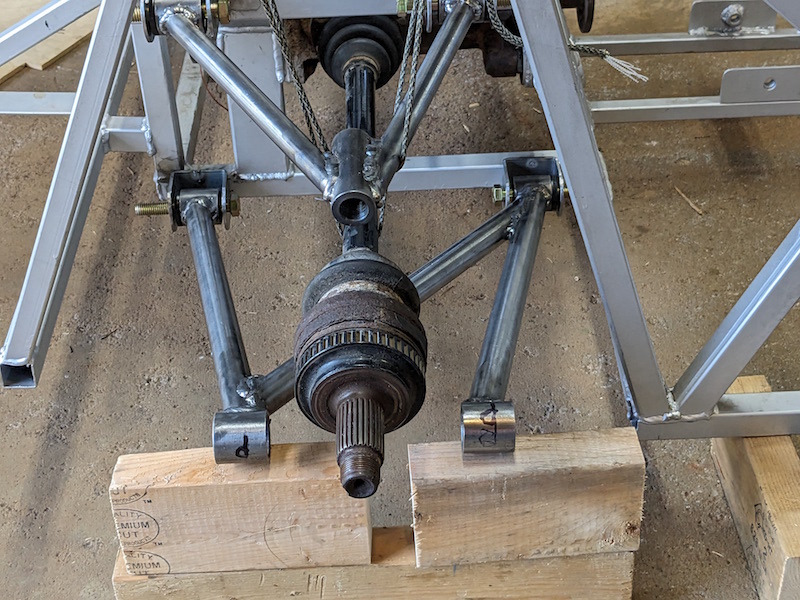
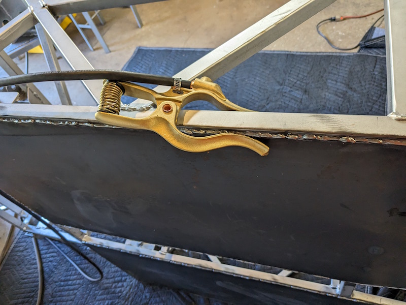
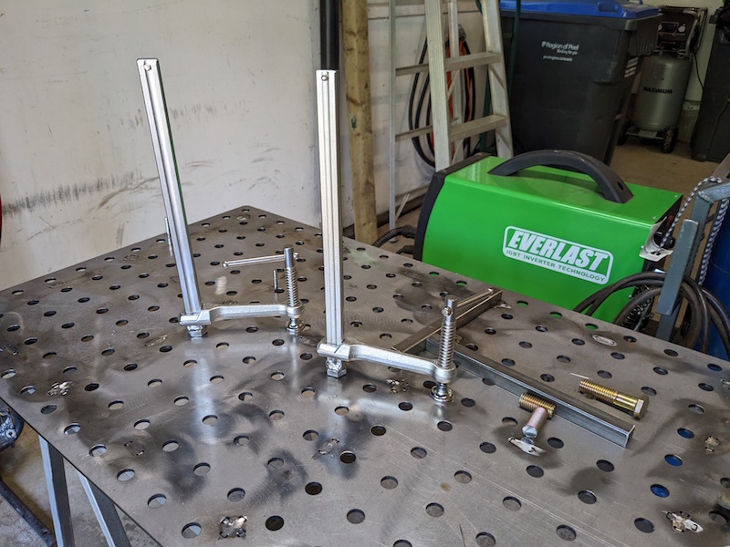
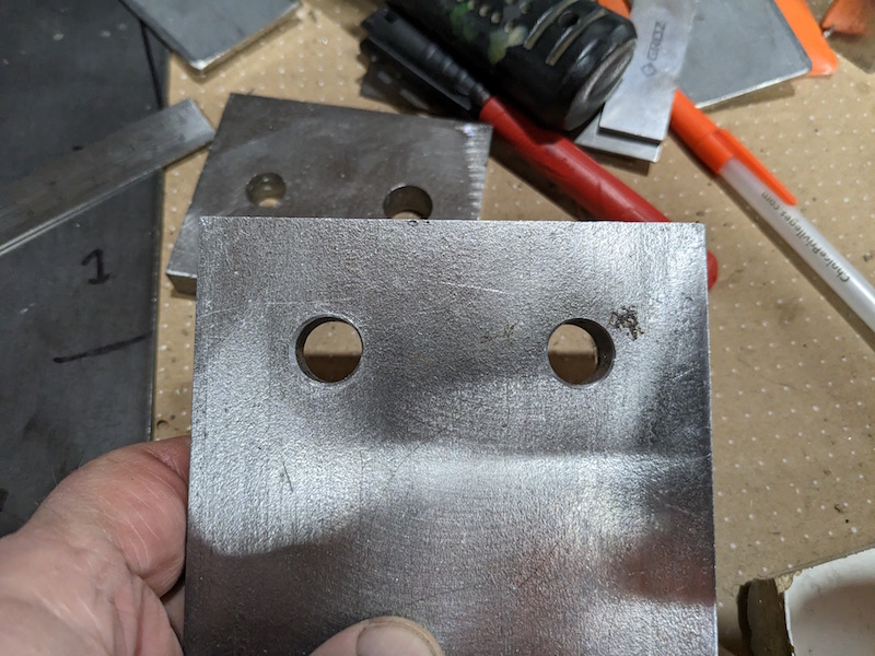
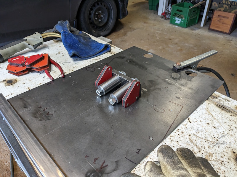
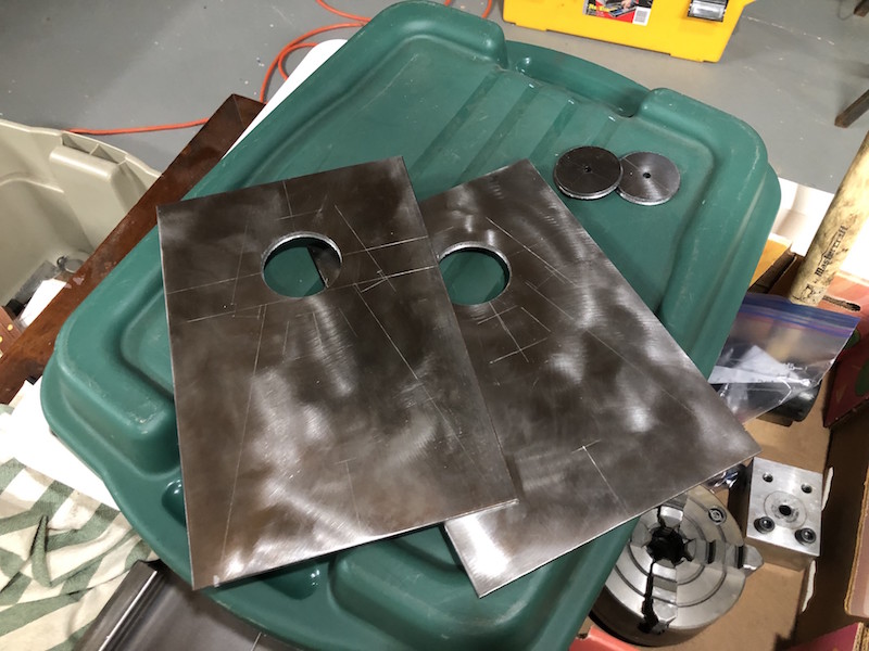
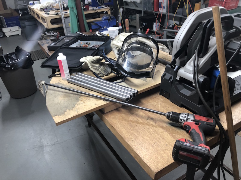
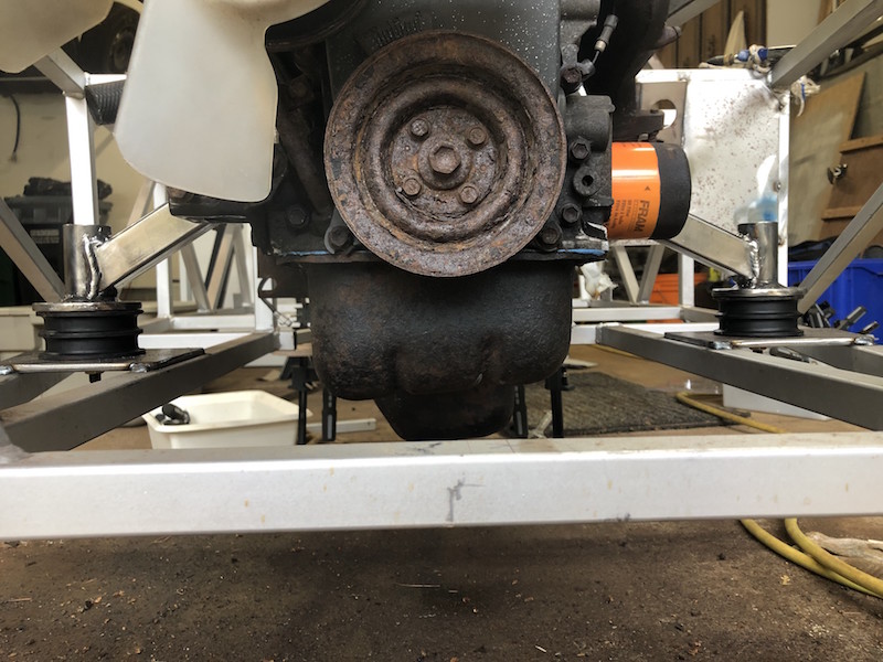
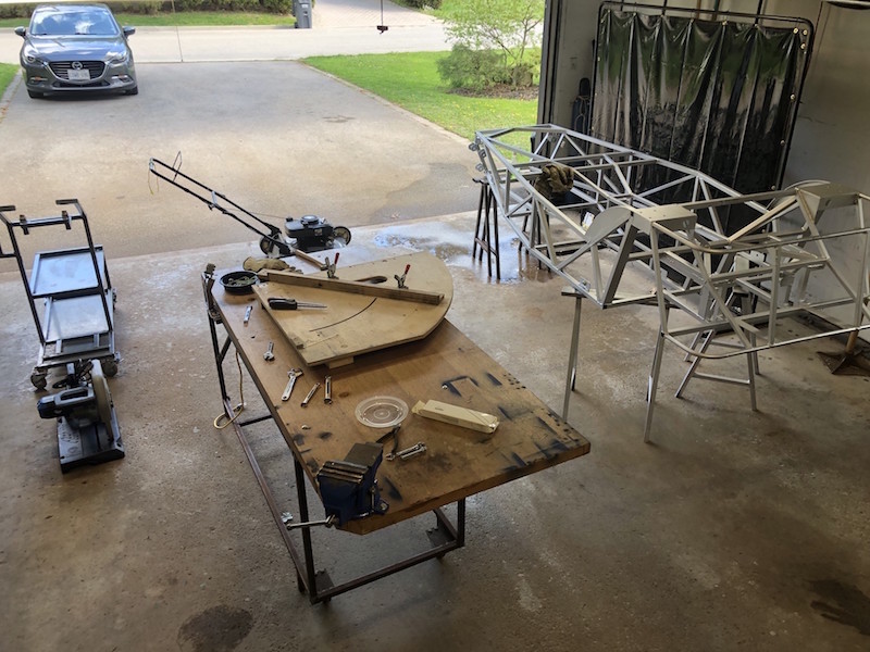
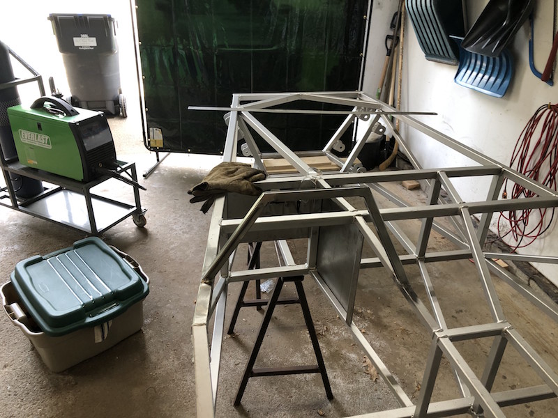
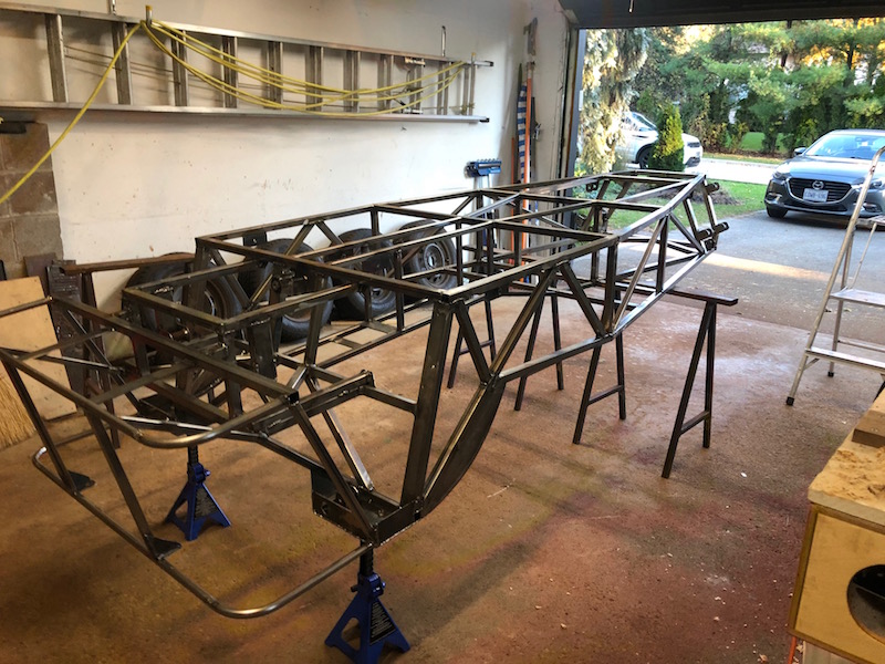
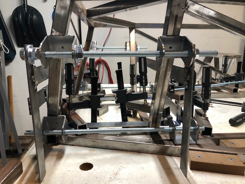
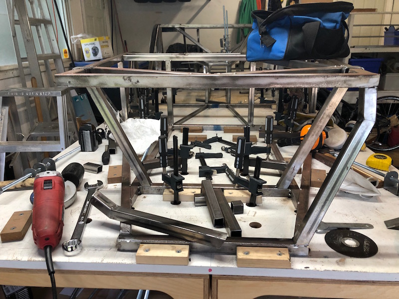
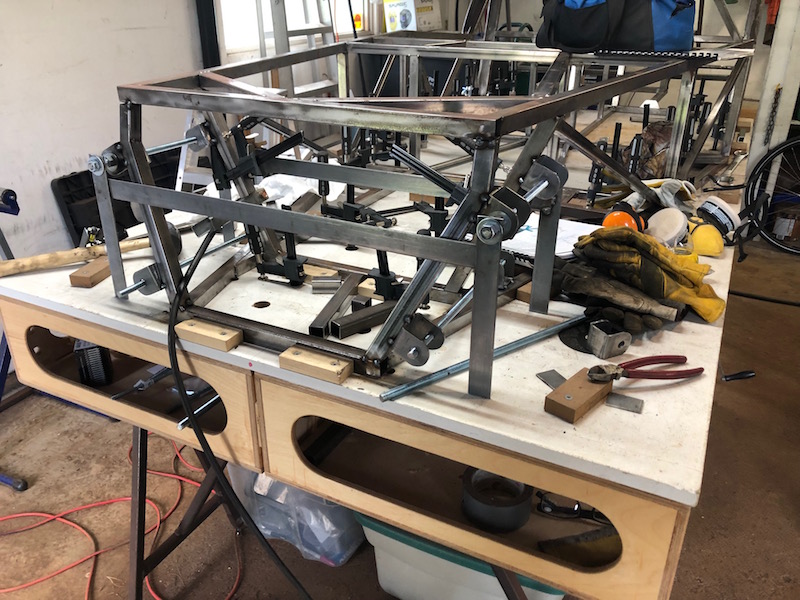
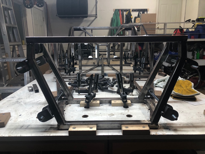
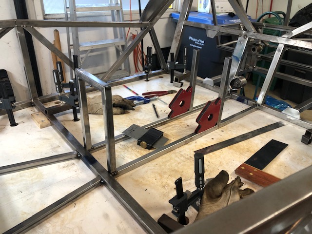
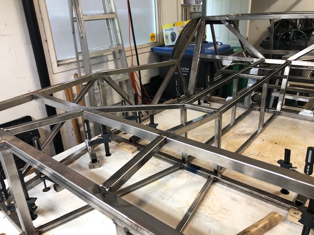
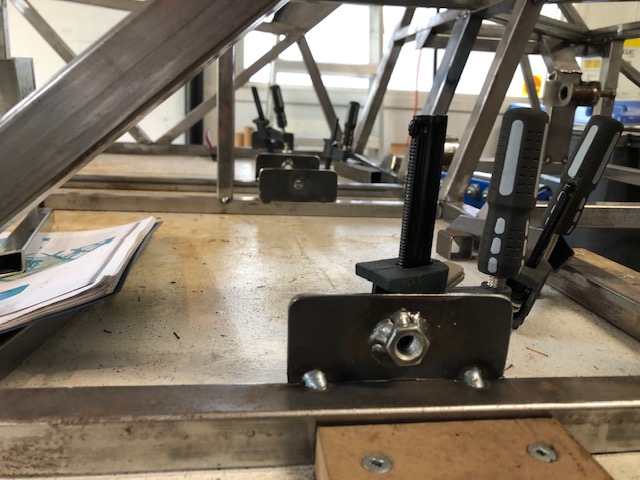
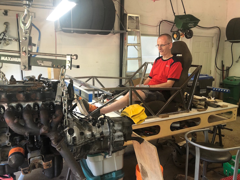
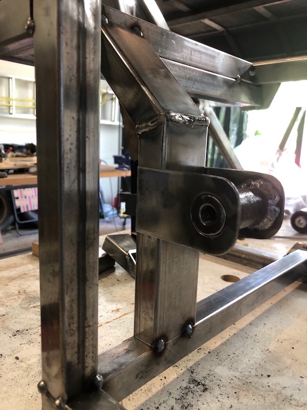
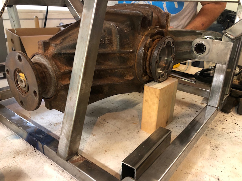
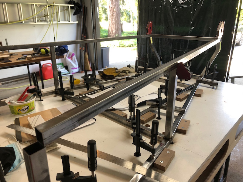
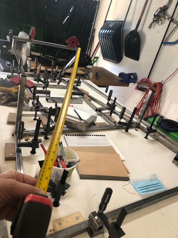
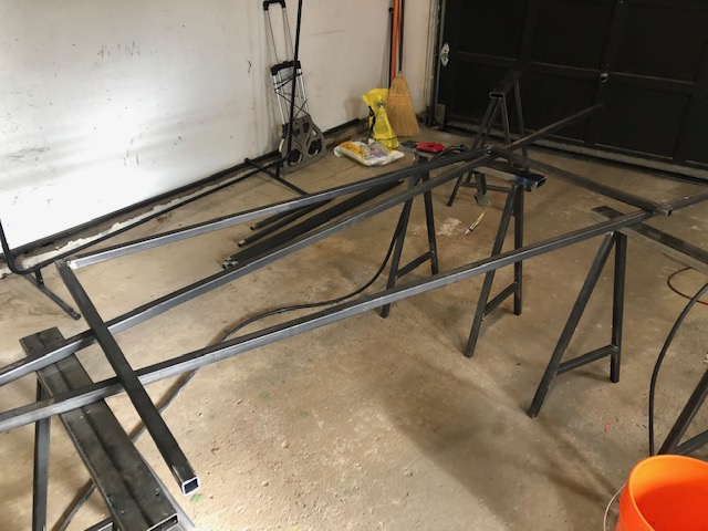
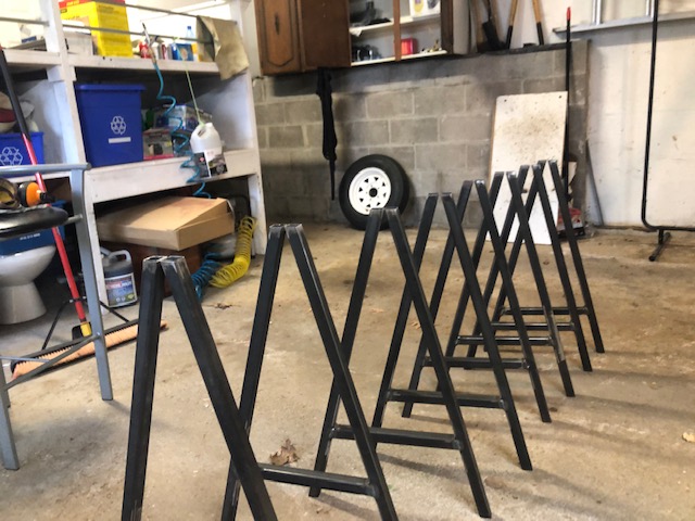
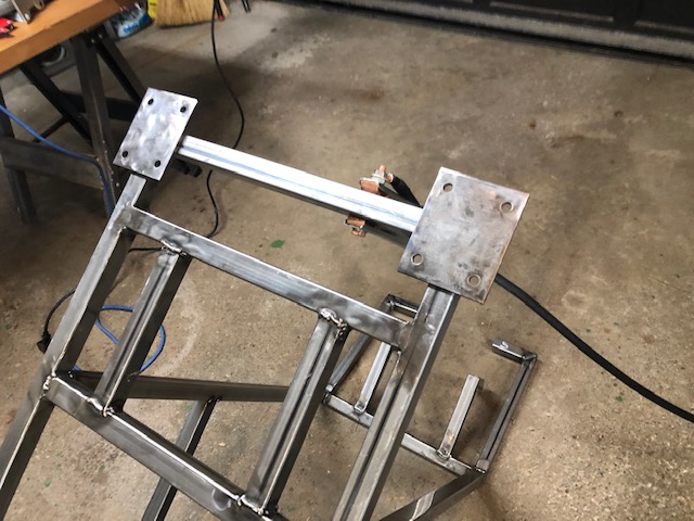
I made a set of suspension side plates that match the hole spacing in the drawing and a couple turnbuckles to take the place of shock absorbers. Now the rear suspension can be assembled around the differential and drive shafts and some serious thinking about the rear hubs can take place.
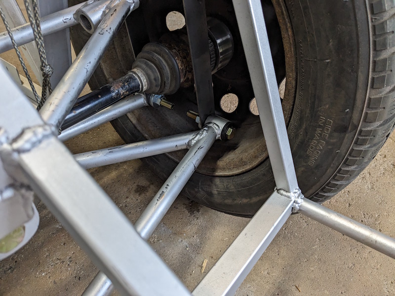
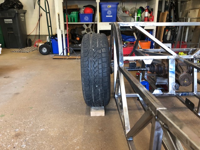
Having the rear suspension assembled is very useful, it allows investigation of suspension clearance with wheels, establishing position of the hubs etc.
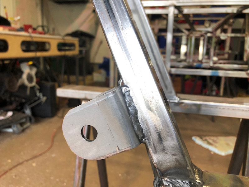
I hope these wishbones fit! What we call control arms the Brits refer to as wishbones and now that they are all fully welded time to see how the front ones fit and time to attach the brackets for the back ones – twice!
The first order of business was to center drill all the bushings to 1/2″. Ultimately the bushings will be drilled to 3/4″ there will be a crush tube (with a 1/2″ id) that will go in the bushing. For now the 1/2″ hole will locate the suspension arms accurately without the need for the crush tube. I used a small arbor press to put in a half bushing on one side of the bushing tubes. These press in “snugly” and will need to be forced out so having one end of the bushing tube open makes that a lot easier.
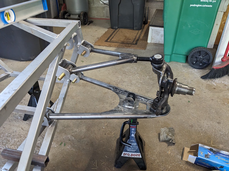
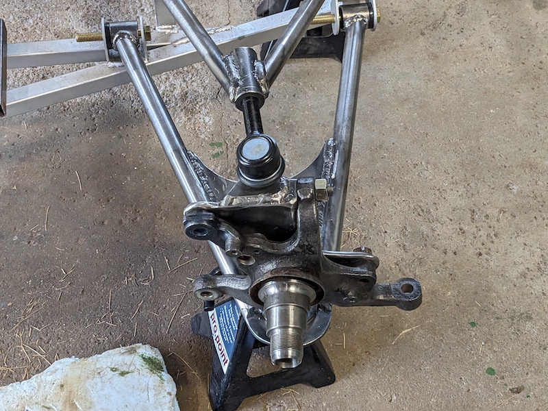
I pressed an old ball joint into the lower front control arm, threaded the top ball joint into the top arm and put it all together on the car frame. This is looking very interesting. The control arms were to match the dimensions in the book but the BMW spindle is different than the book’s donor car. Hopefully there will be enough engagement of the threaded upper ball joint into the control arm.
I assembled the front suspension for the drivers side and everything checked out there as well.
At this point the rear suspension mounting brackets had not been positioned and welded ton the frame. Since the differential differs from the doner vehicle in the book I could not just use their locations.
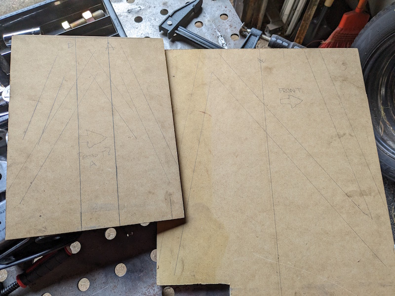
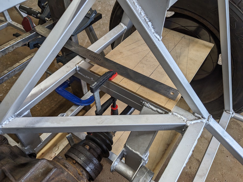
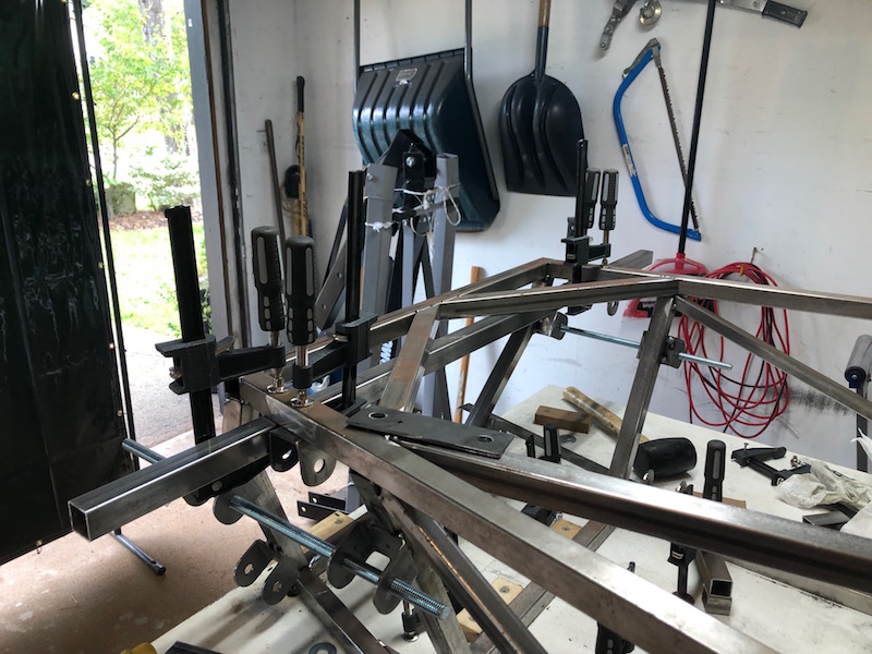
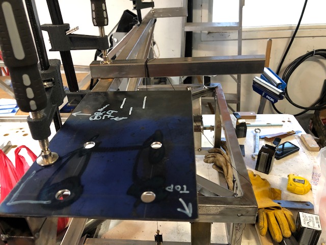
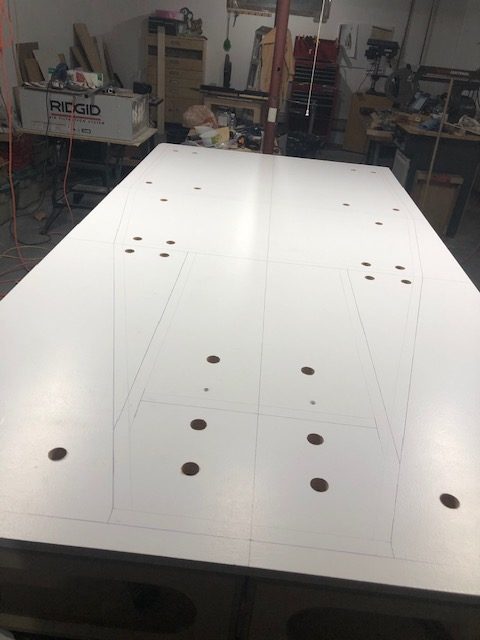
I created a couple hardboard templates to show the locations of the bracket center lines. I could clamp these onto the frame,align them with the center line of the driveshafts and mark the location of the brackets.
This worked out pretty well to align the brackets and control arms except for one small problem…
The upper control arm extends too far from the frame because I welded the brackets on the side of the upper frame member rather than the bottom surface (Arggghhhhh, I hate it when I do stuff like that…). Well I will have to think about this for a while, I have other things to do.
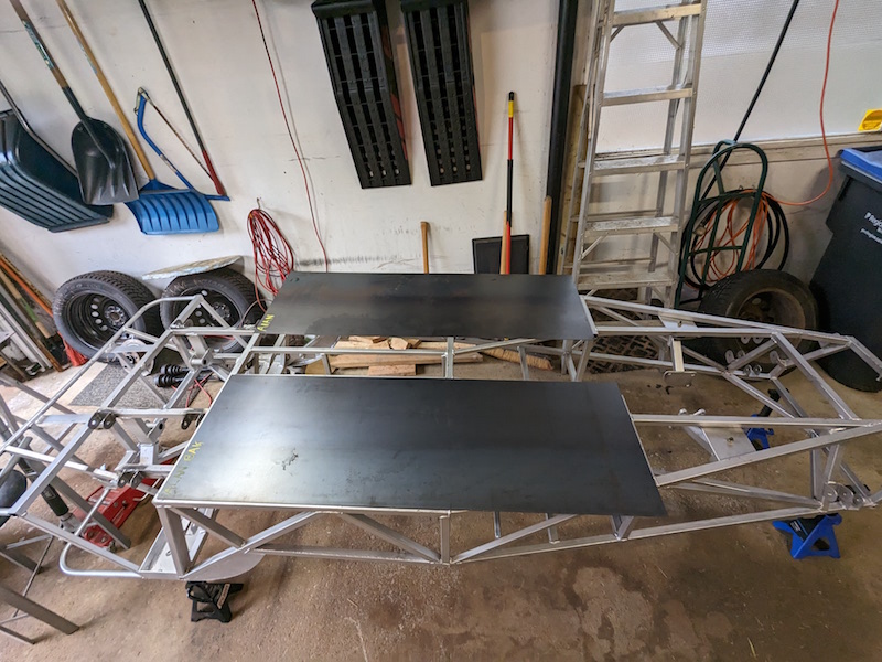
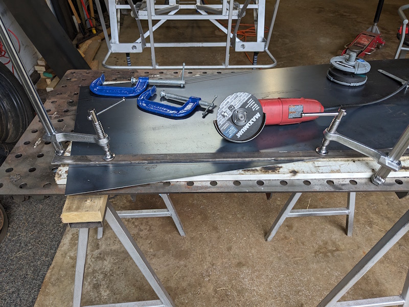
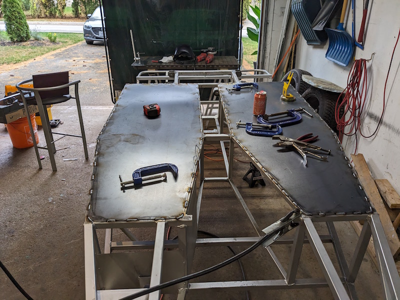
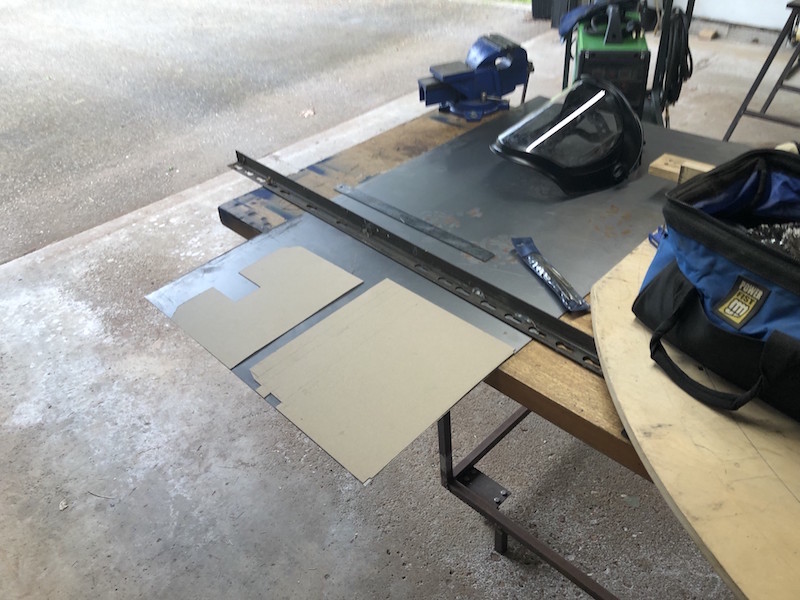
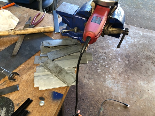
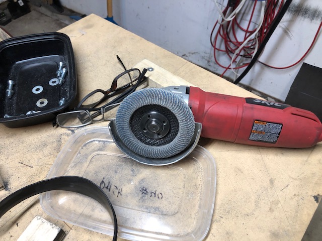
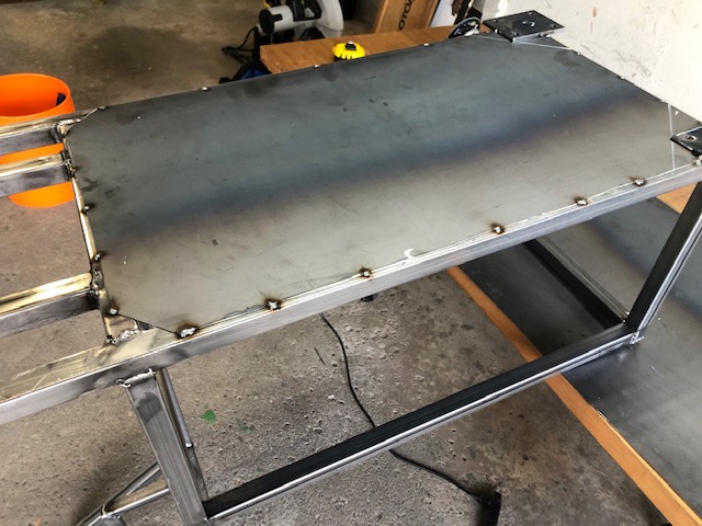
I decided to go with 16 ga. steel for the floor pans of the Locost. It is heavier than aluminum but it’s stronger and can be welded onto the frame. The added weight is located as low in the frame as possible. Rectangular sheets were measured marked and trimmed with the angle grinder.
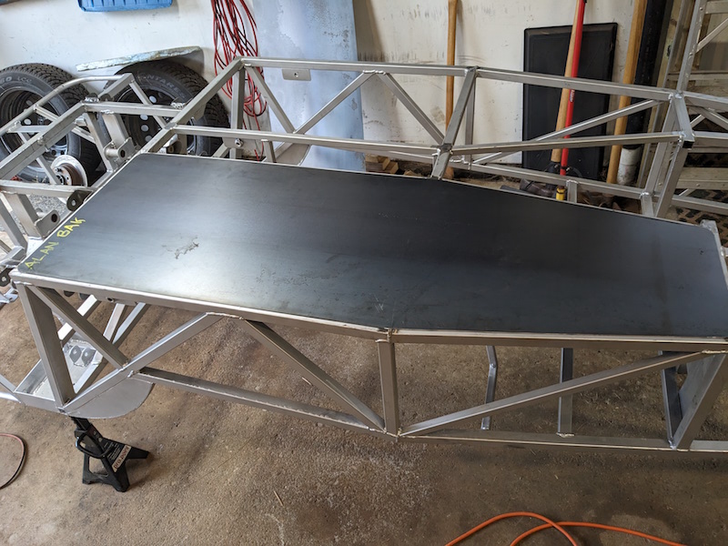
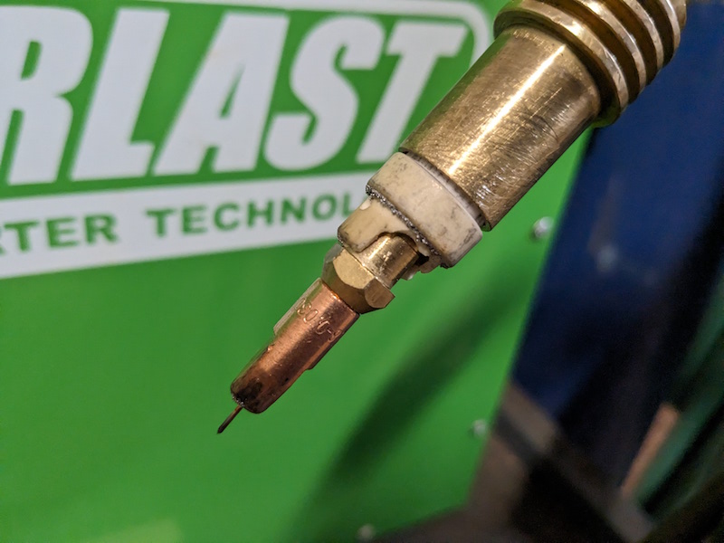
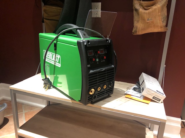
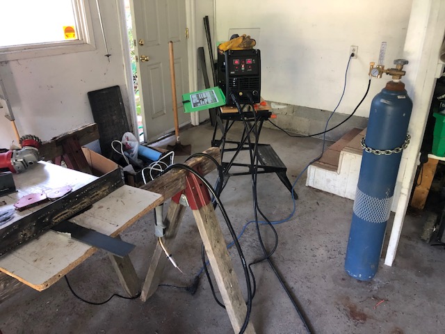
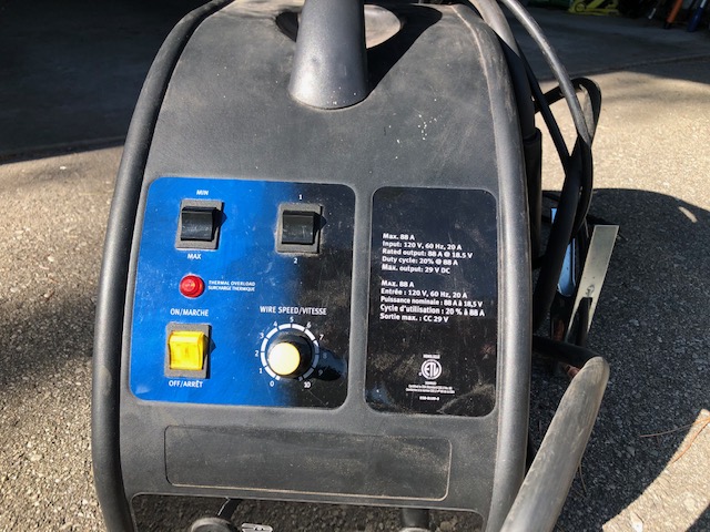
While I was getting ready to weld the floor pans I discovered an issue with the welder . A ceramic spacer in the nozzle was chipped so I made a trip to Everlast and picked up a couple along with a enhanced ground cable. I made a few passes around both of the floor pans stitching them until they were continuously welded onto the frame.
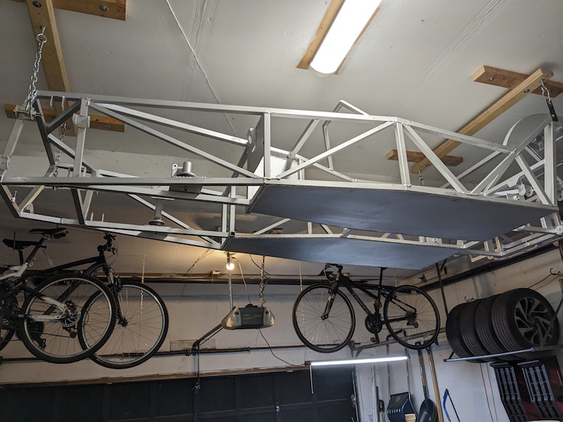
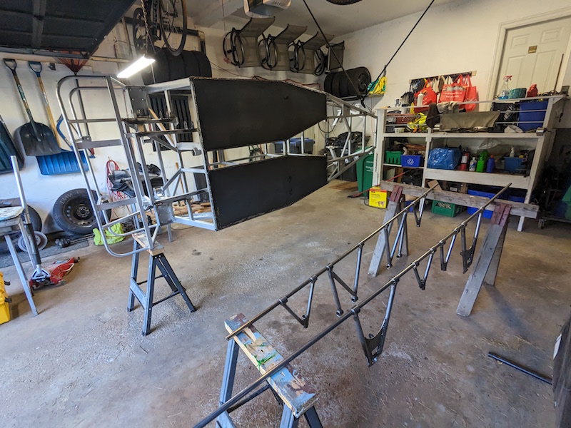
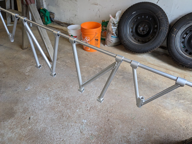
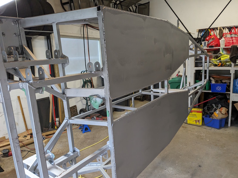
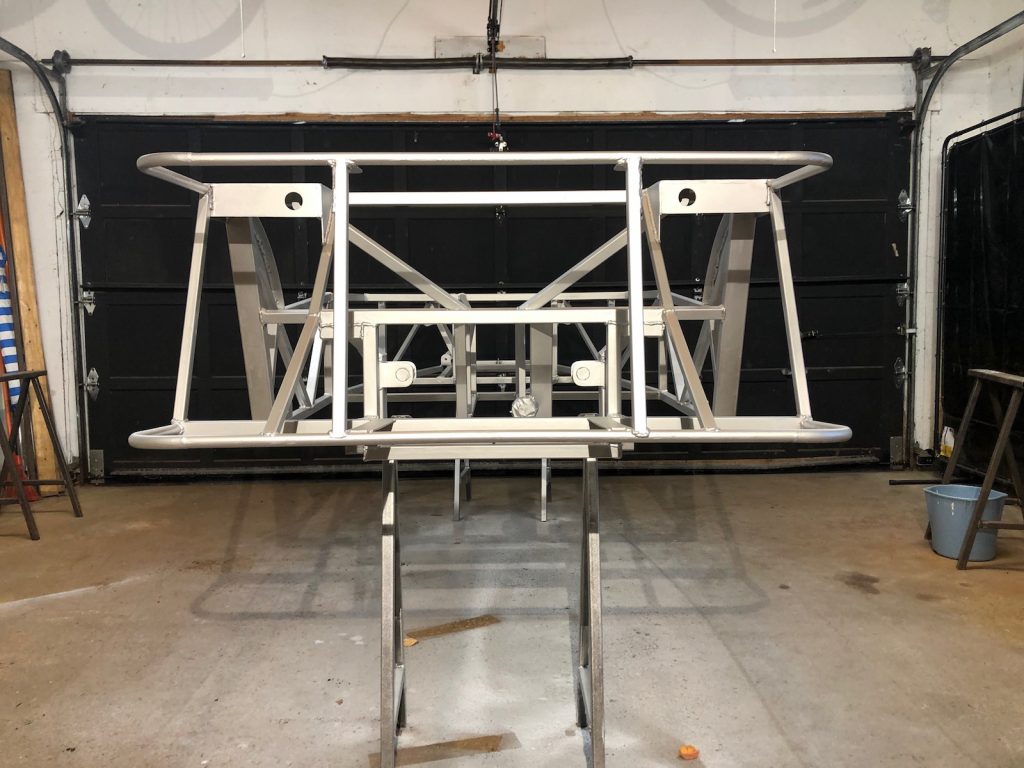
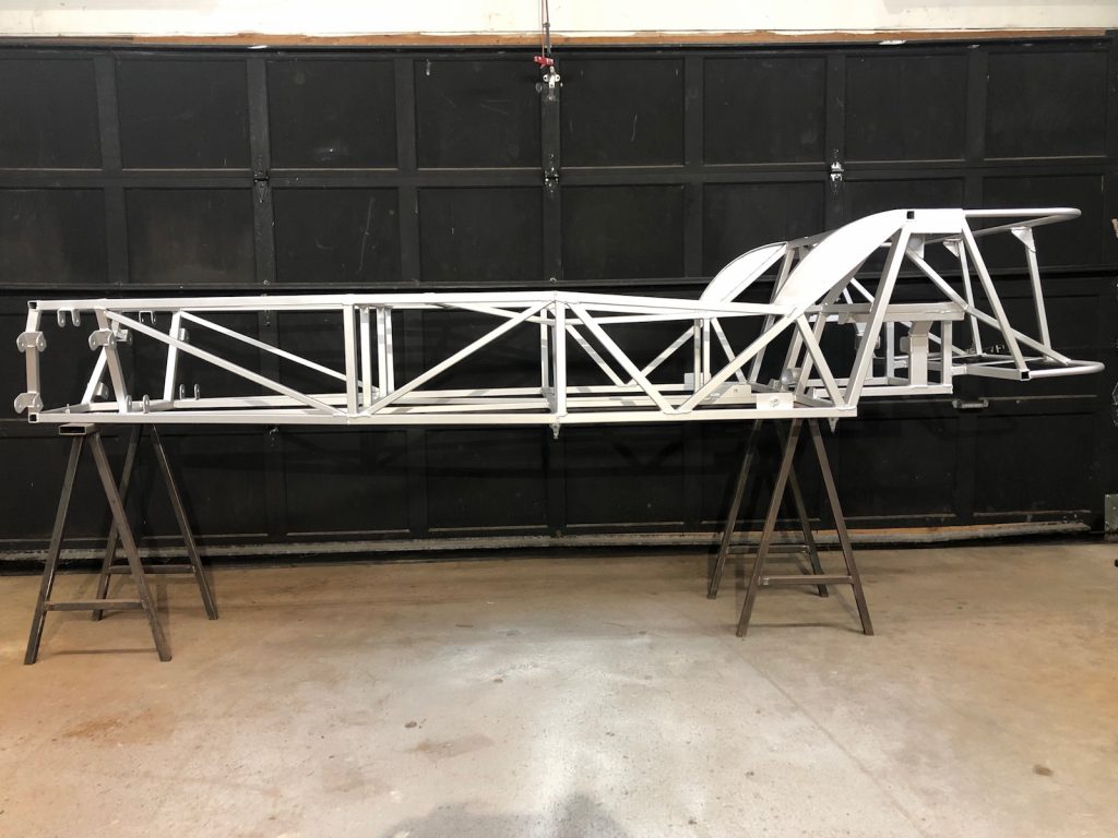
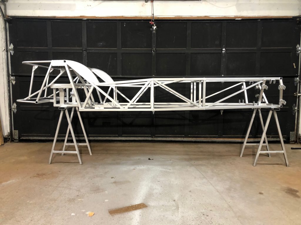
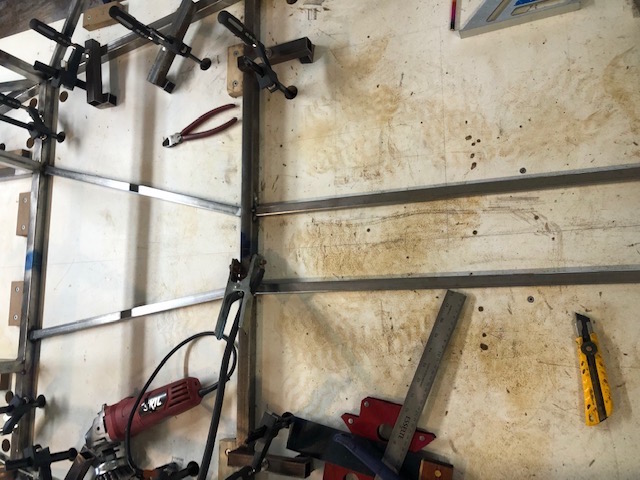
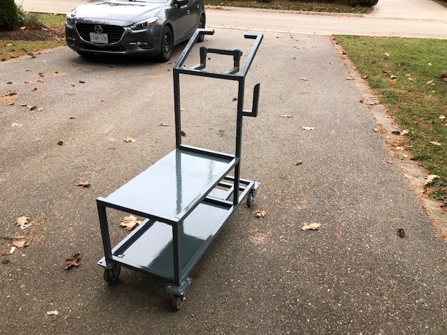
Time to get a coat of primer on all that unprotected new metal. I hung the frame up on it’s side so it would be easier to paint both surfaces of the floor pans. At the same time I hung up all the control arms to give them a coat of primer as well.
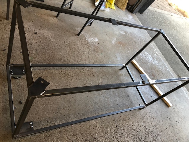
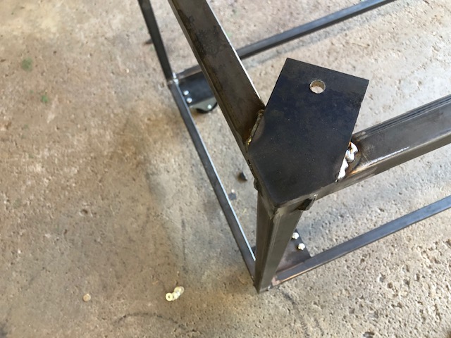
Time to fix those “miss installed” suspension brackets. I had extra brackets so I decided that the best plan was to cut the arms of the original brackets and put the brackets where they should be. Looks a bit ugly until you get a coat of primer on it !
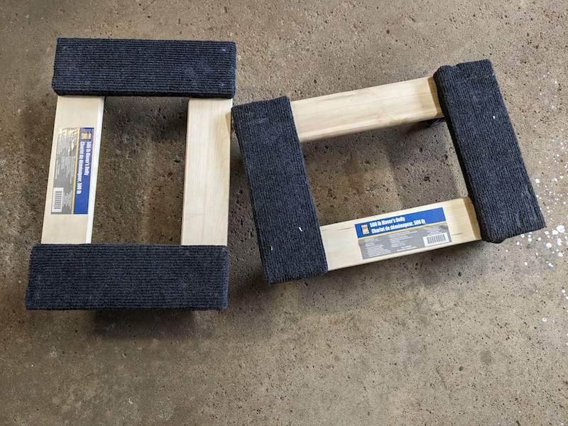
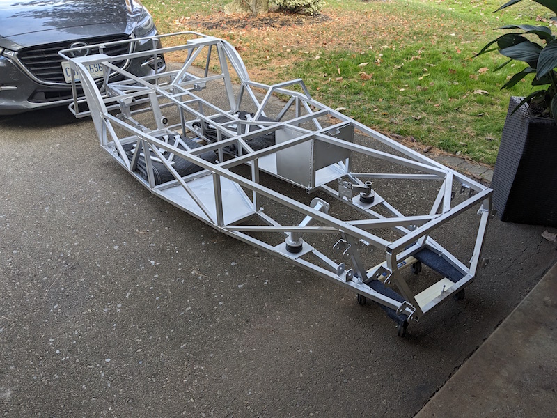
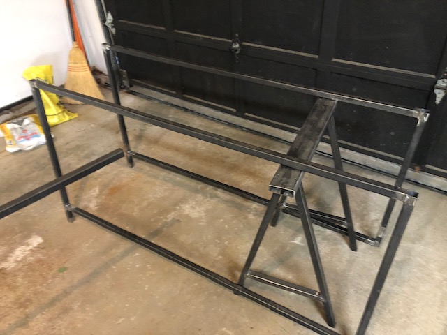
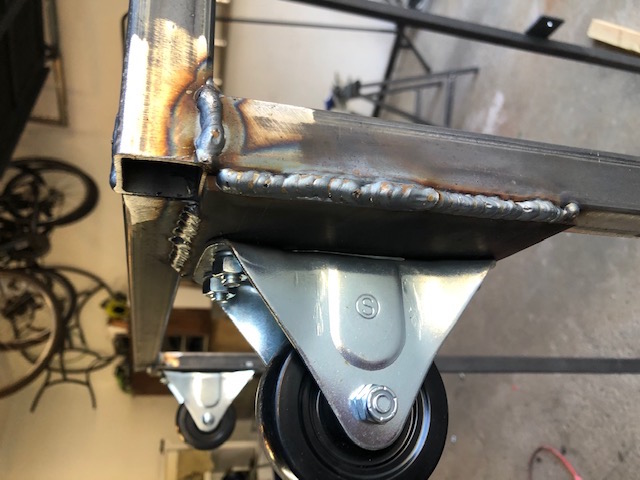
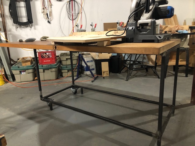
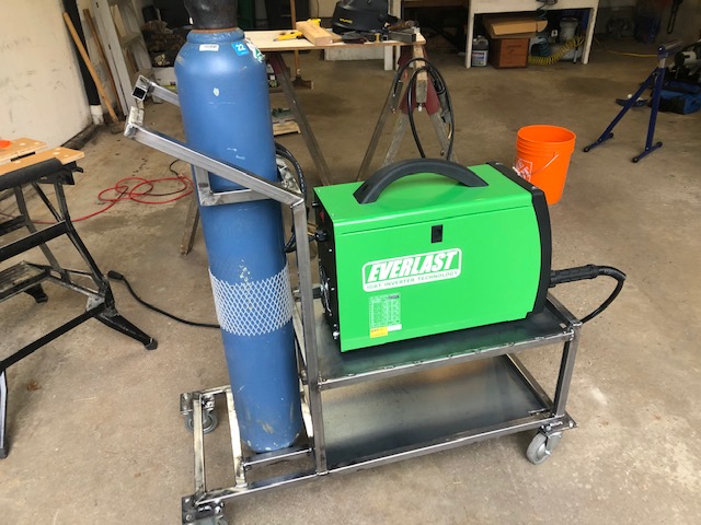
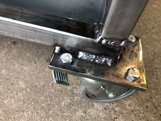
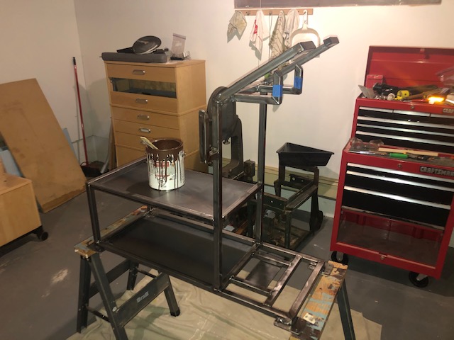
I picked up a couple moving dollies because the frame is weighing about 185 lbs so it makes it easier to move.
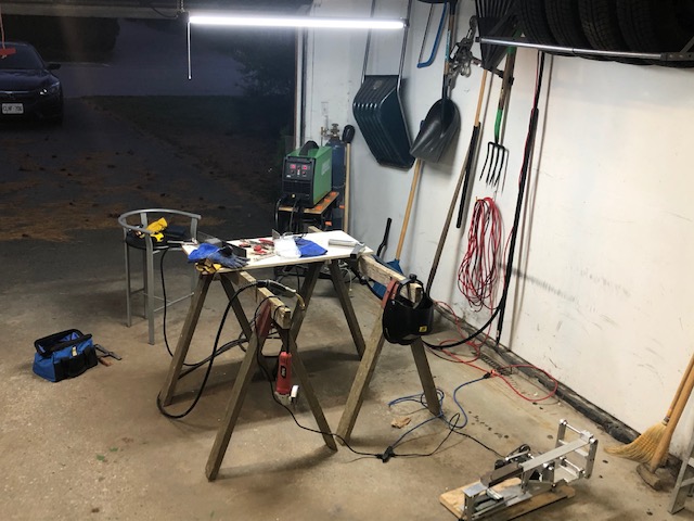
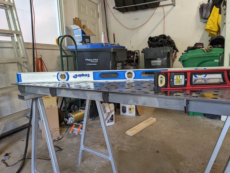
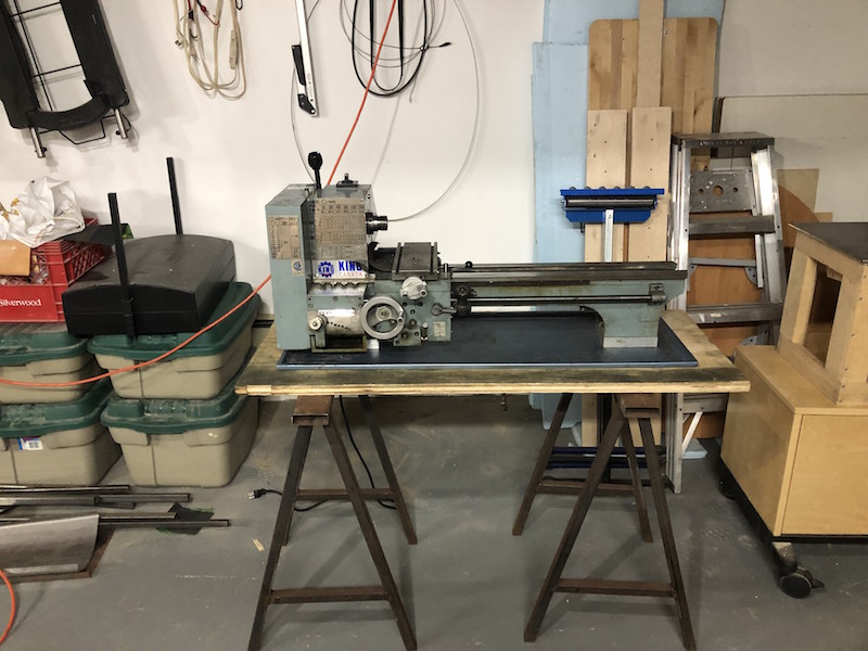
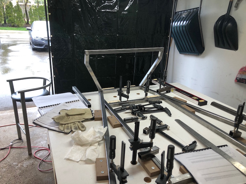
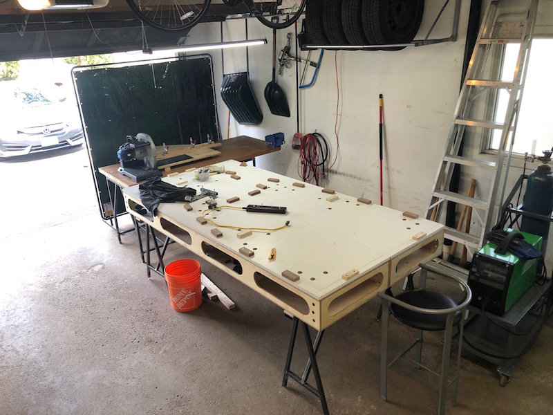
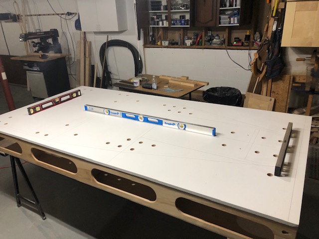
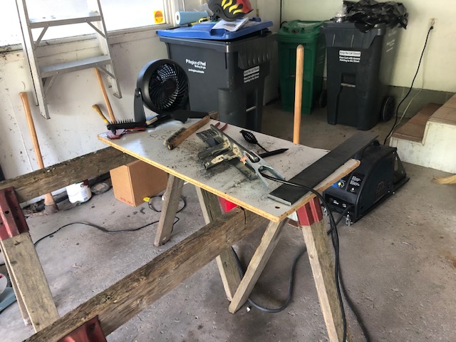
This is my original welding table, an old piece of particle core sheet on a couple even older sawhorses. Needless to say this is not ideal, getting a good ground on smaller work pieces is challenging and constantly putting out fires is distracting. When the CertiFlat 2’x4′ welding table went on sale at Princess Auto I rushed out and bought one
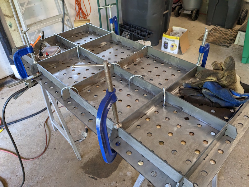
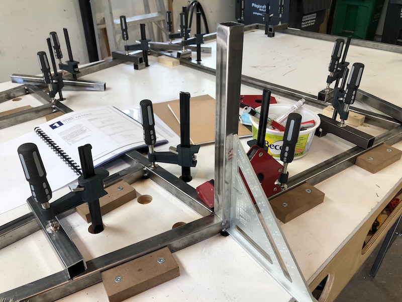
All the table parts are laser cut for a perfect fit. The procedure is to lay the top, with the crown down, on a table or across a pair of sawhorses. The lattice of support beams are then arranged on what will be the bottom surface of the table. There are tabs on the beams and slots in the table top that they engage with. U-bolts (and some clamps) are used to draw the table top onto the support beams at all intersections. The beams are then tacked onto the bottom surface of the table top. The table can now be flipped over and checked for flatness.
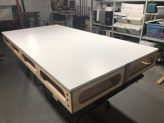
All the tabs and slots are now welded and any welding lumps created are carefully ground off. The table weighs about 100 lbs. which is not massive but flatness is maintained by the rigid perfectly straight beam structure under the top rather than by the thickness of the top. Very clever.
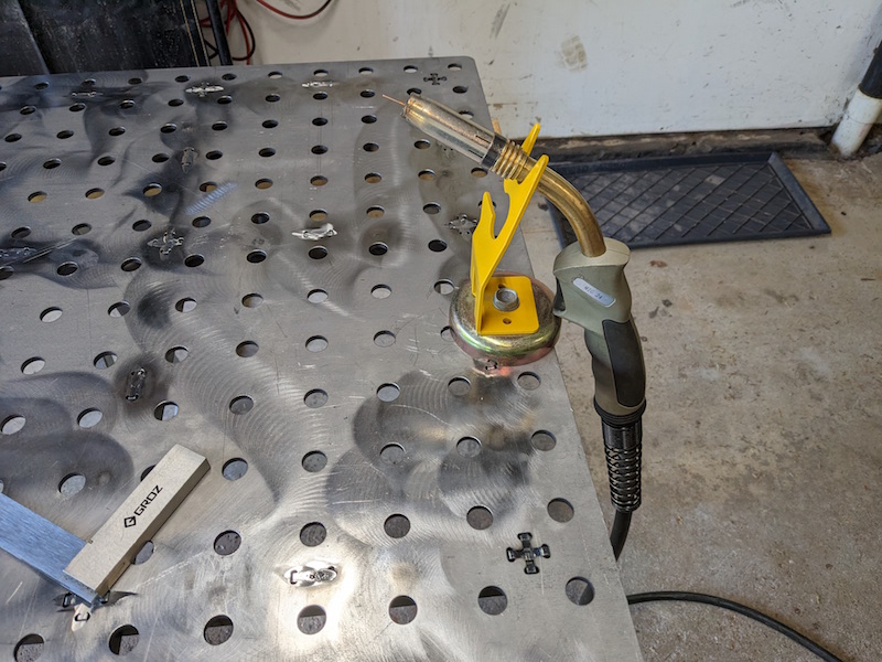
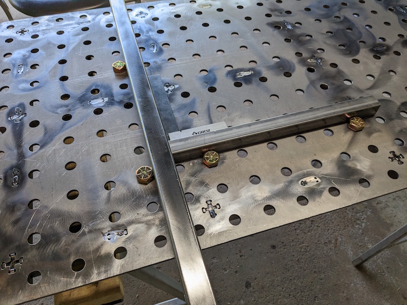
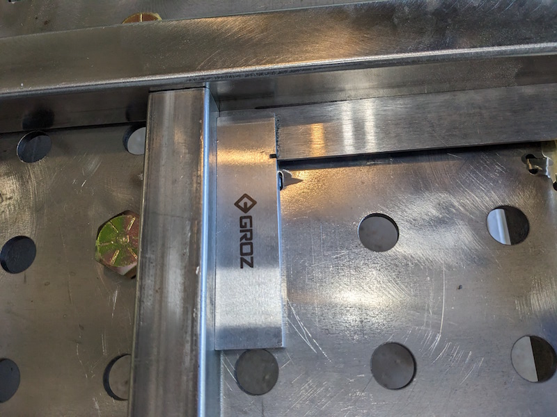
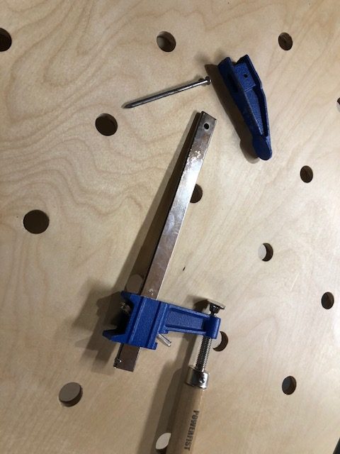
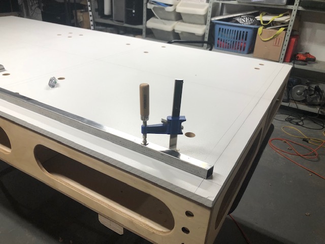
Because the hole pattern in the top is very accurately cut fixtures can be used to simplify set-up and fabrication. Some 3/4″ bolts dropped through holes in intersecting rows creates a perfect 90 degree angle. The holes can also be used to locate clamps anywhere on the surface. Time to make some fixtures.
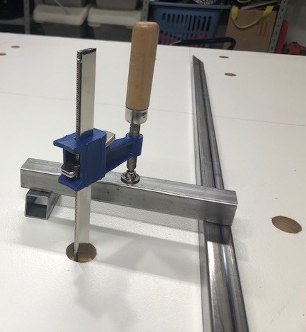
I cut the foot off of a couple heavy welding clamps, welded a 3/4″ bolt on the end and then chopped off the threaded piece.
These can now be put in an hole on the table and used to clamp a work piece.
A handful of the Harbor Freight clamps volunteered for welding table duty as well. The mechanics are a bit different, a slot is cut in the bolt head, the end of the clamp thinned and welded into the slot.
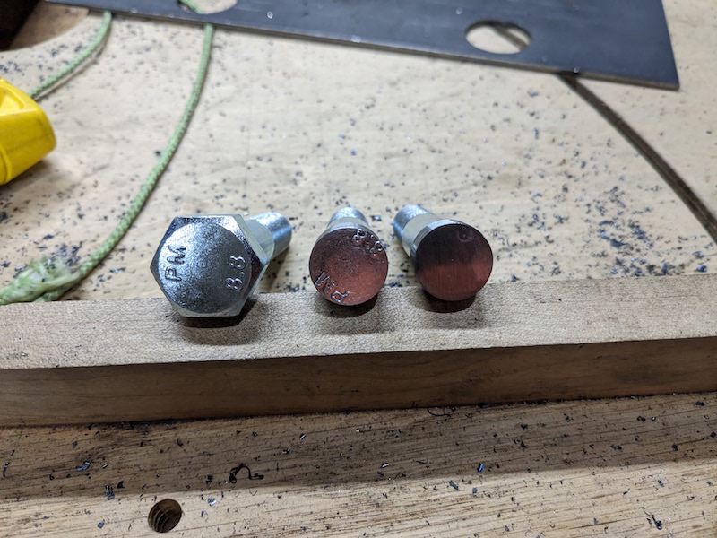
Time to make some posts for the table. I turned the heads of some 3/4″ bolts so they fit inside a bit of leftover 1″ DOM tubing. I then welded the tops and touched up the posts with the angle grinder.
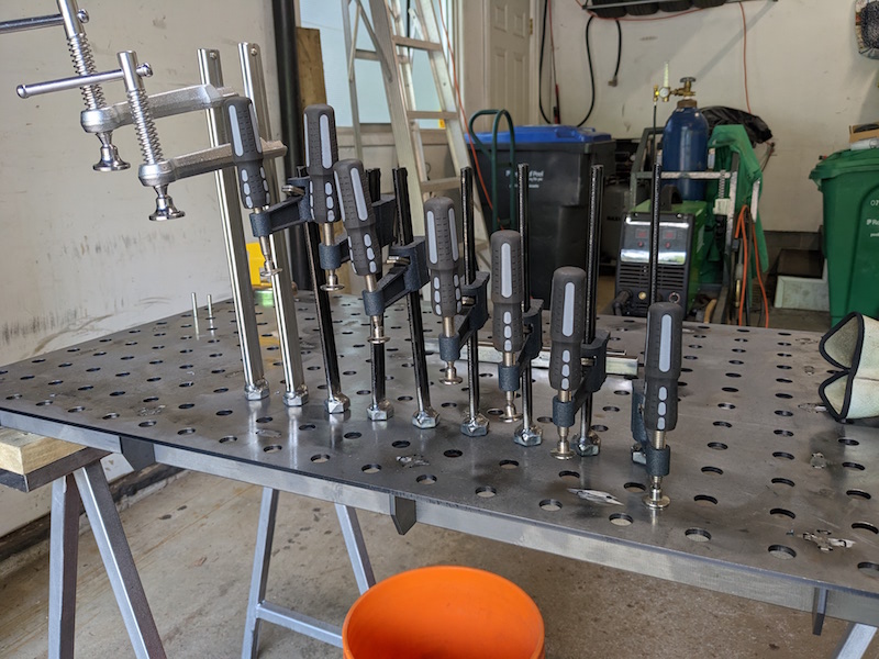
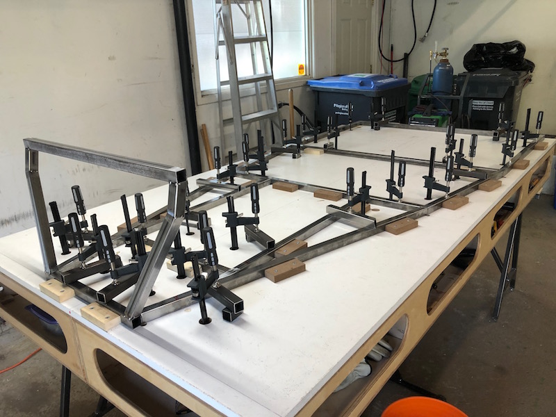
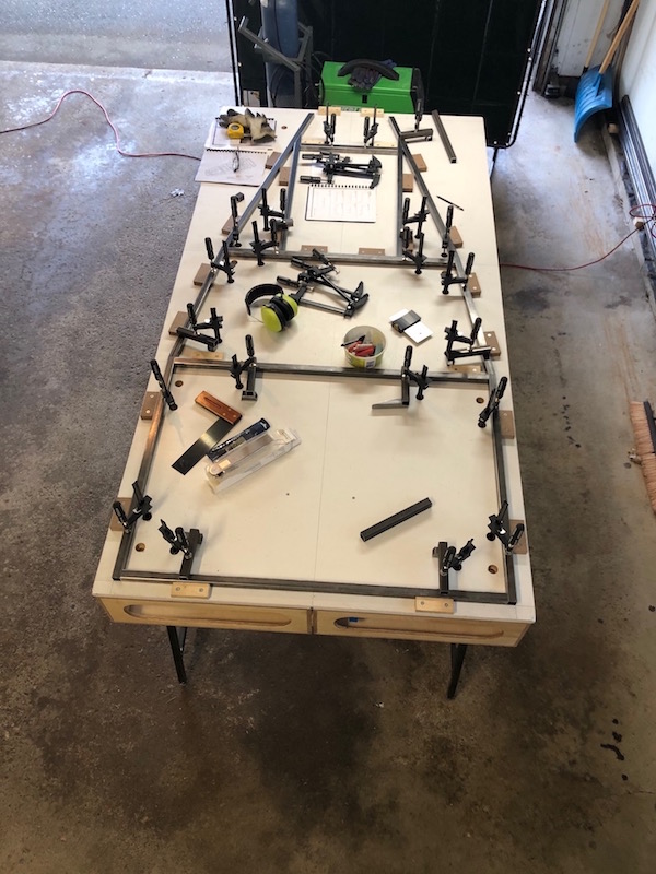
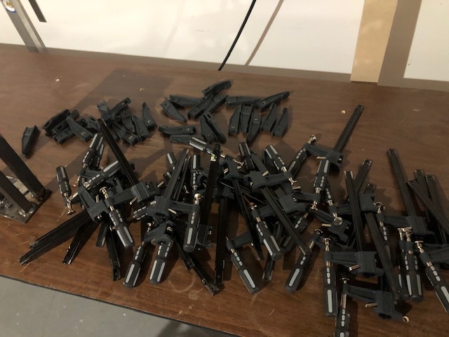
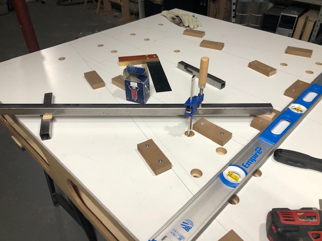
Now I have plenty of tools for the table, time to use them on all the control arms that have been waiting to get fully welded.
Using all of those new tools to secure the control arms for welding.
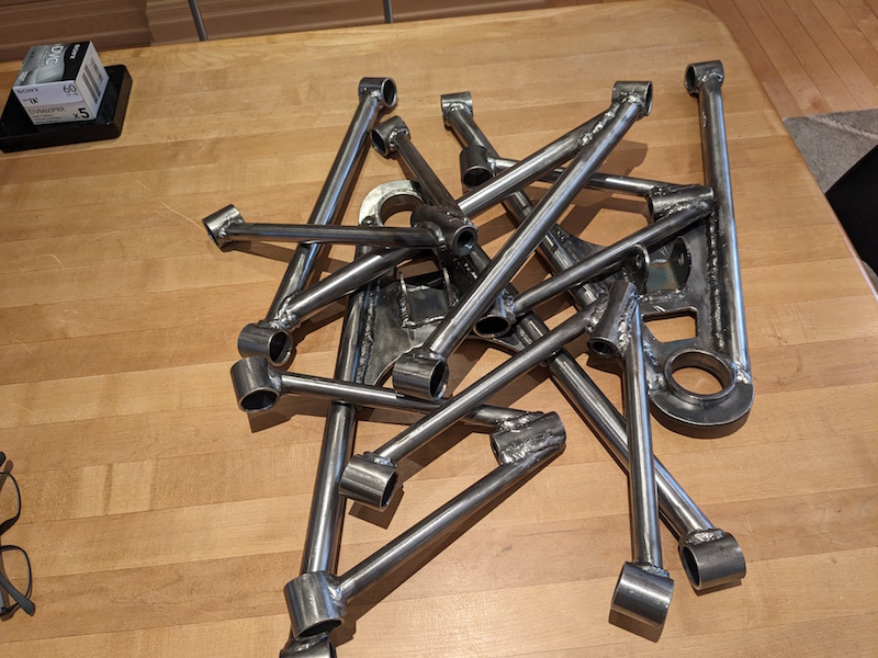
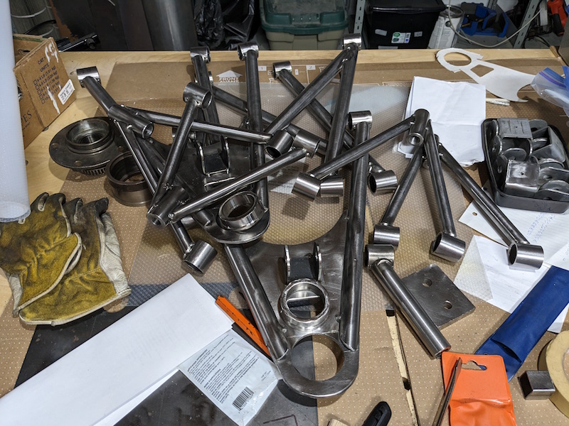
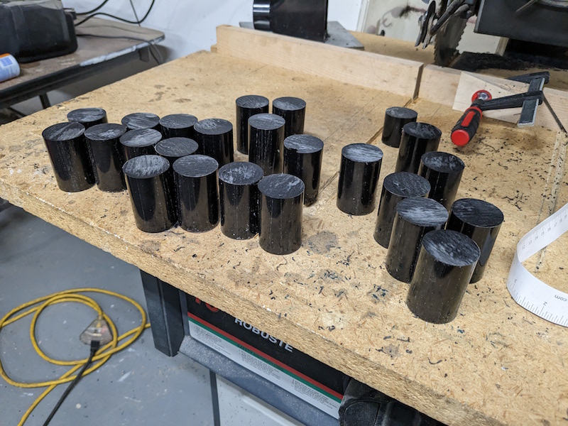
Time to make bushings for all of those control arms.
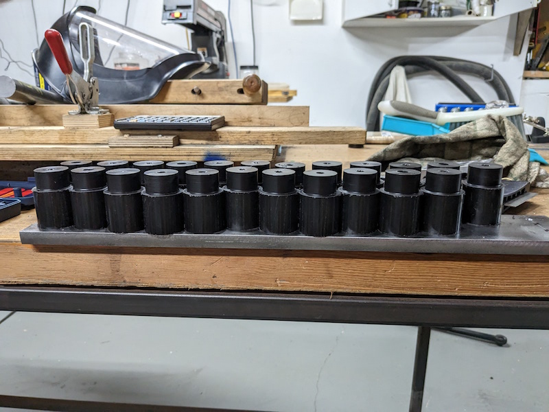
Here are the bushings required for the car, they are split so two are required for each bushing tube. Here are all the control arms with bushing tubes attached, we are going to need a lot of bushings!
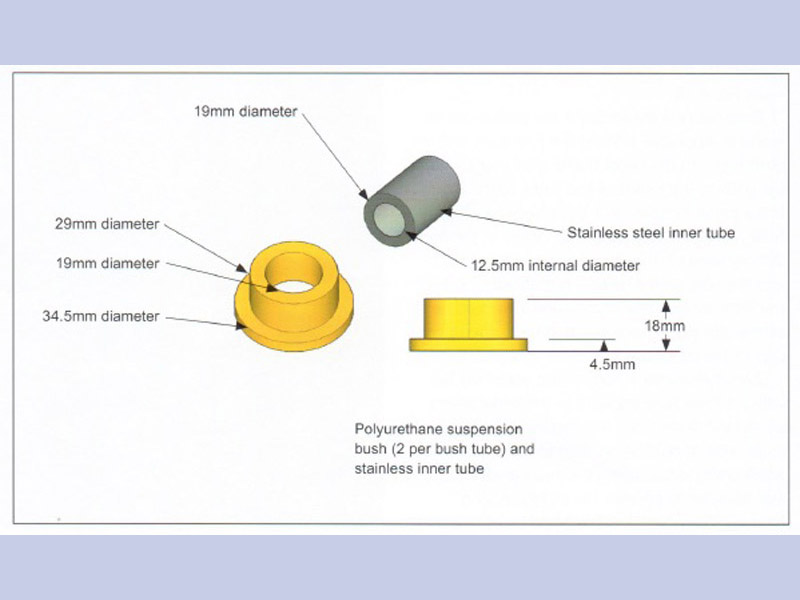
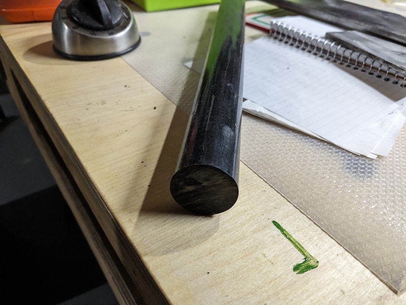
The book calls for Polyurethane material but it is difficult to machine at the hardness required. Polyurethane could be mixed in liquid form and pored into bushing shaped molds but since I don’t have any molds we will be substituting. Delrin is a harder plastic that is easier to machine, it’s self lubricating and is available as round rod. That’s what I’ll be using.
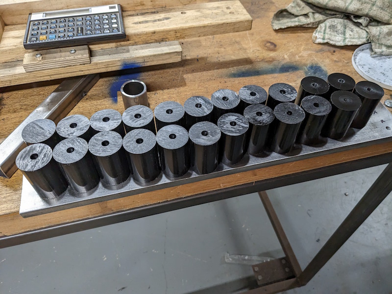
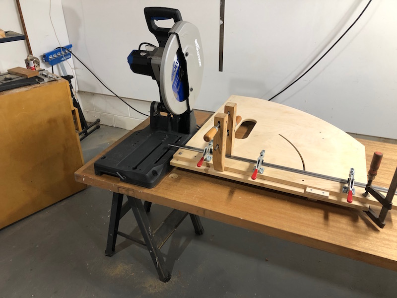
I started by cutting the rod into pieces using a radial arm saw. Each piece is long enough to make 2 bushings. I then center drilled them and faced the ends in the lathe.
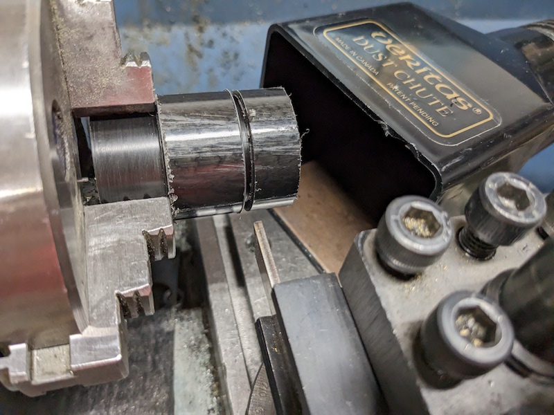
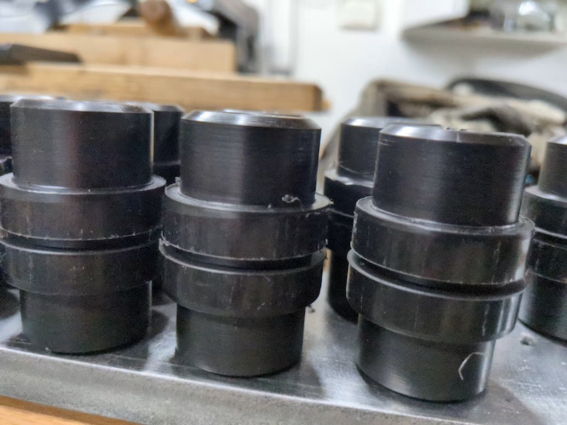
Next I used a parting tool to to cut the relief that defines the shoulder of one bushing and turned that end down to size.
Now I could flip each blank around use the parting tool to define the other bushing shoulder and turn the end other down.
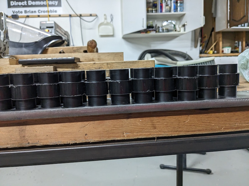
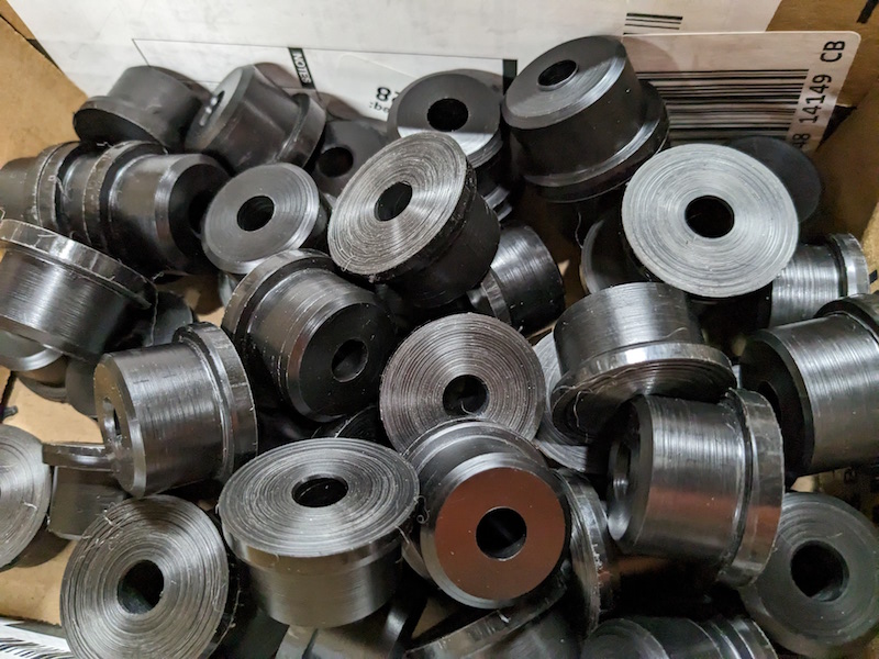
The parting tool marks the cutoff point for the 2 bushing halves but before splitting them I beveled the corners to make it easier to press them into the bushing tubes. There you have it a bushel of bushings.
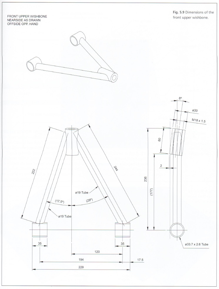
In the tradition of saving the worst till last, I give you the front upper control arms.
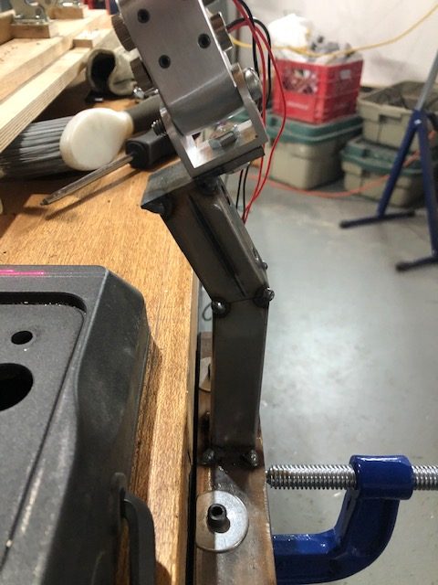
The issue with these control arms is that the threaded tube that holds the upper ball joint is offset 8 degrees. I will need to do some “innovative lathe work” as my tube notching attachment is designed to make notches that have zero degrees offset. This design also means that we need a more complicated jig as the left and right hand pieces are unique cannot be flopped from side to side (because of the offset).
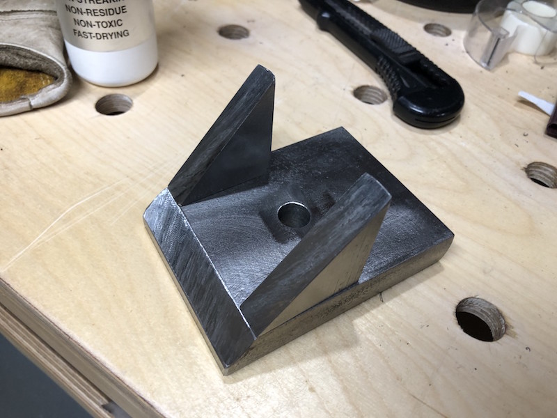
This jig is similar to the one used for the rear upper control arms with a couple exceptions. We are using 1/2″ plate and need to cut 8 degrees off the edge of the upright so that the threaded ball joint holders are not held horizontal for assembly. Instead of making two jigs (right and left) we can use one with 2 positions for the threaded ball joint holder. Finally, we trim the plate to length.
Here is the single jig that can locate a ball joint holder in one of 2 positions at the required 8 degrees off the horizontal. Now, how to cut the 3/4″ tubes to connect to it?
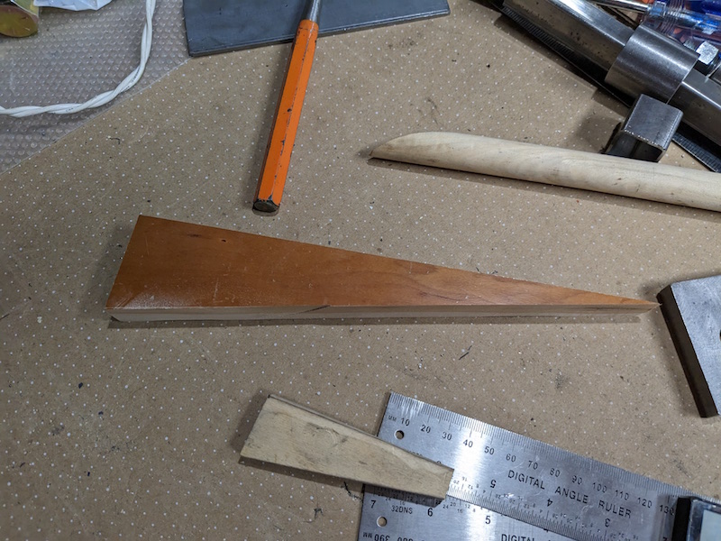
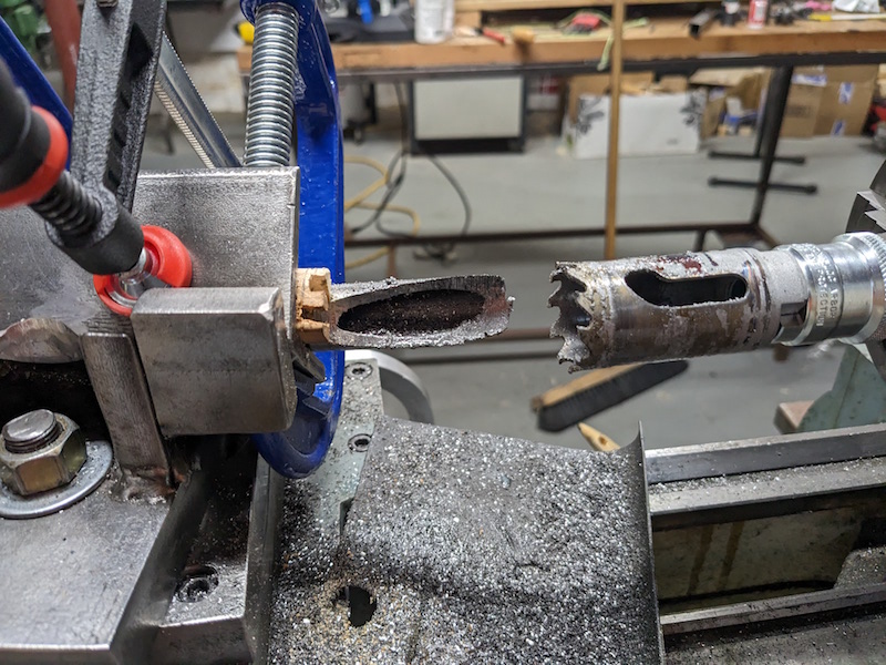
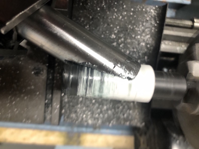
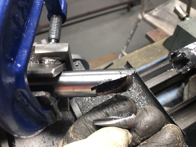
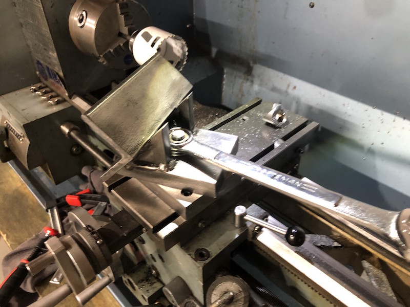
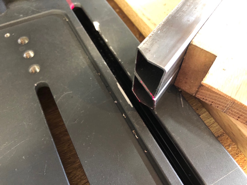
My solution was to cut a wedge to use in the tube notcher to create the offset. The wedge is not 8 degrees because the angle iron faces are at 45 degrees so some trigonometry was used to come up with the right angle (11.3 degrees I think). The right image shows how the wedge is used and the precarious job of clamping the tube in place.
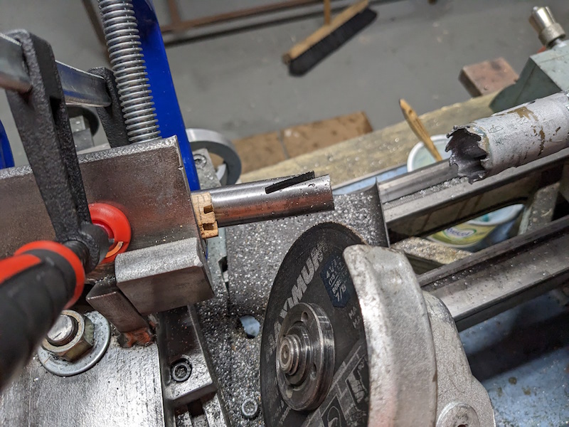
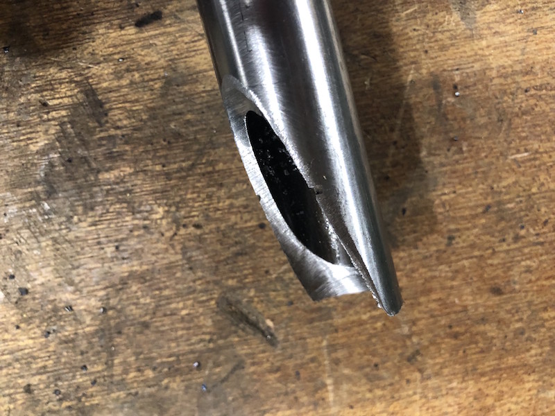
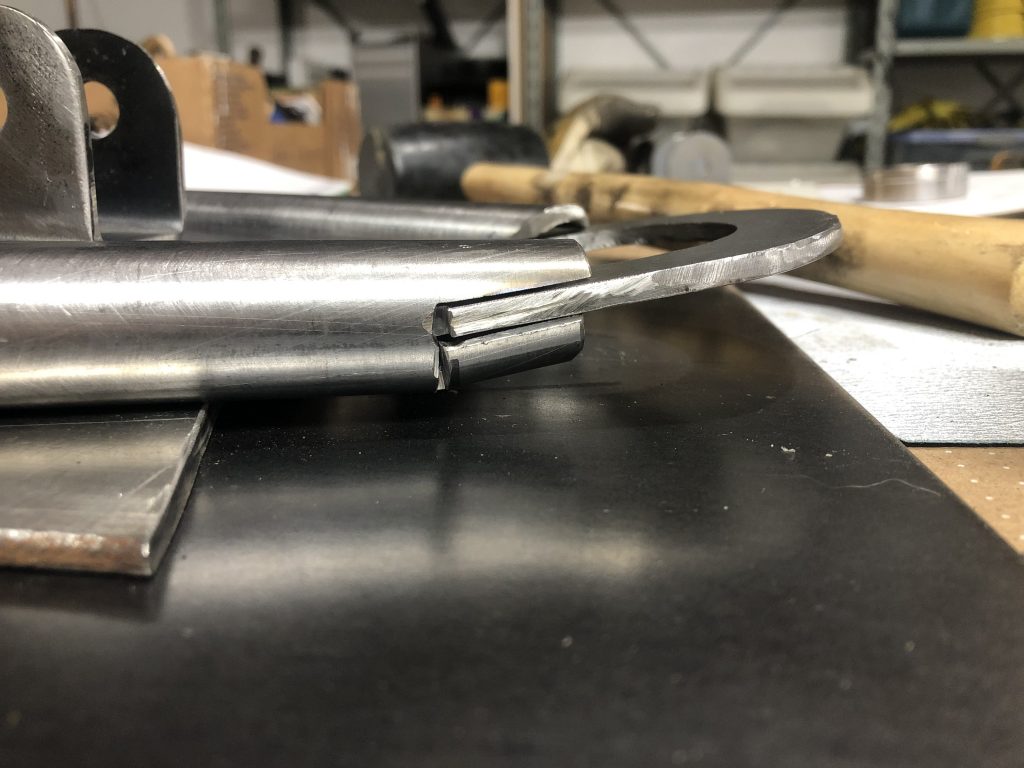
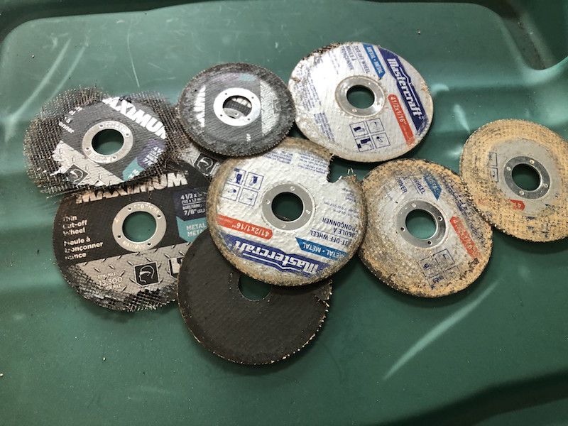
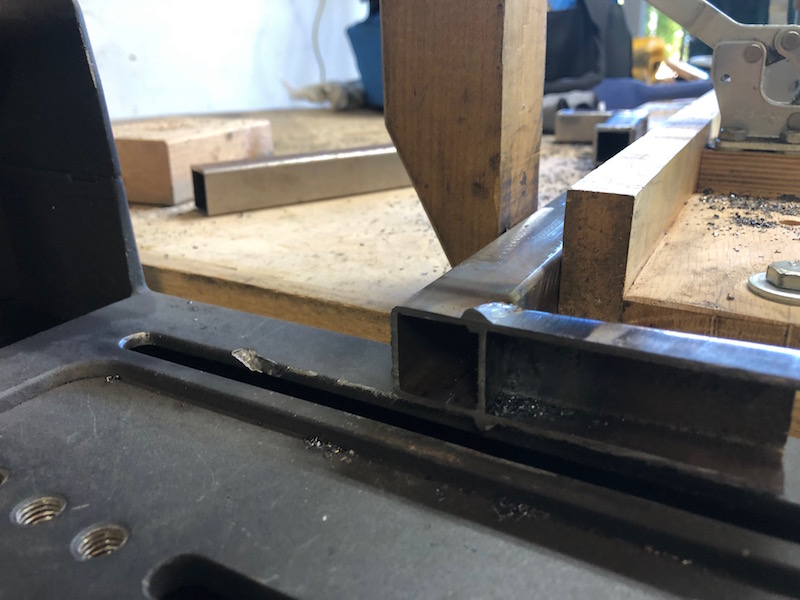
Cutting is very slow going and again the cut bottoms out in the hole saw and needs to be cleared before finishing. The results are good but the process is a bit scary.
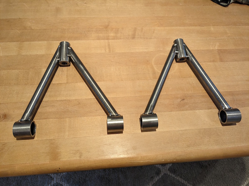
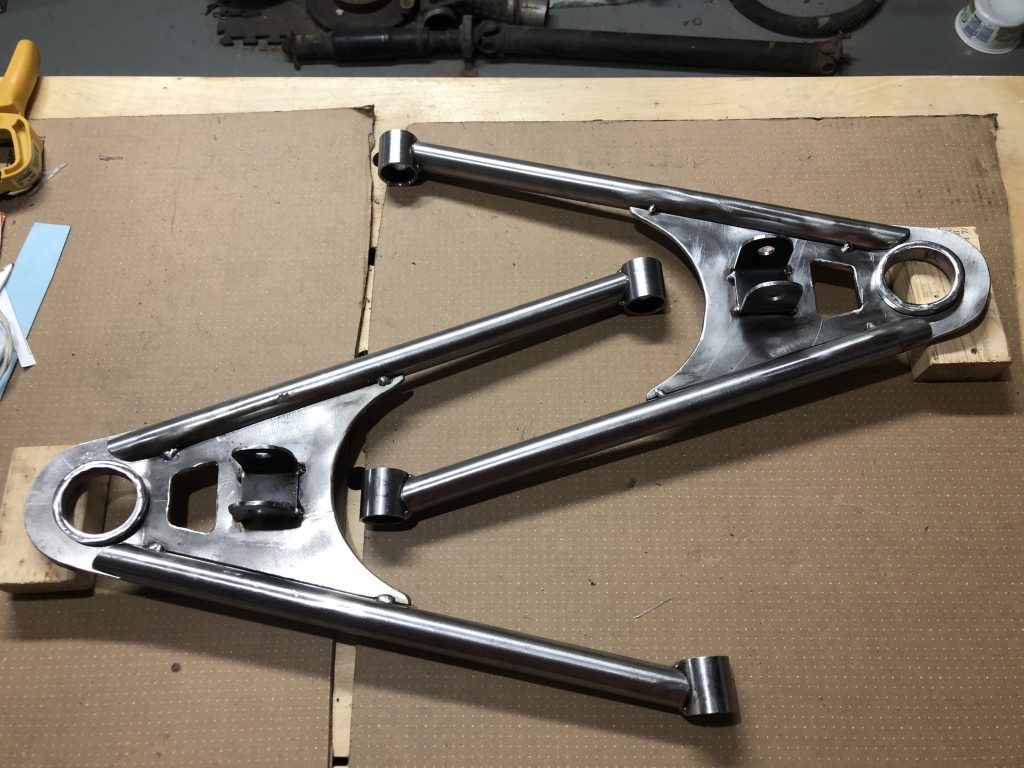
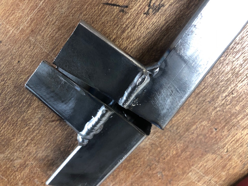
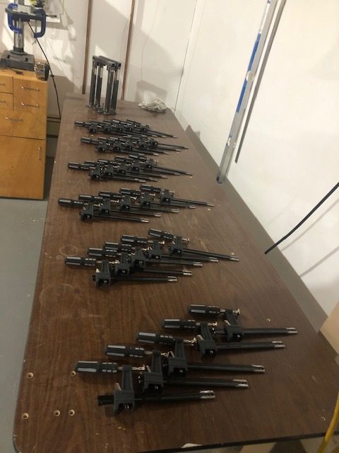
Now we can use the jig to set up each of the control arms and tack weld them. That is a lot of work for 8 degrees!
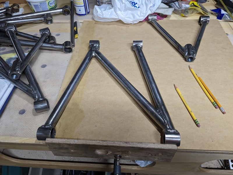
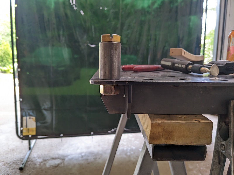
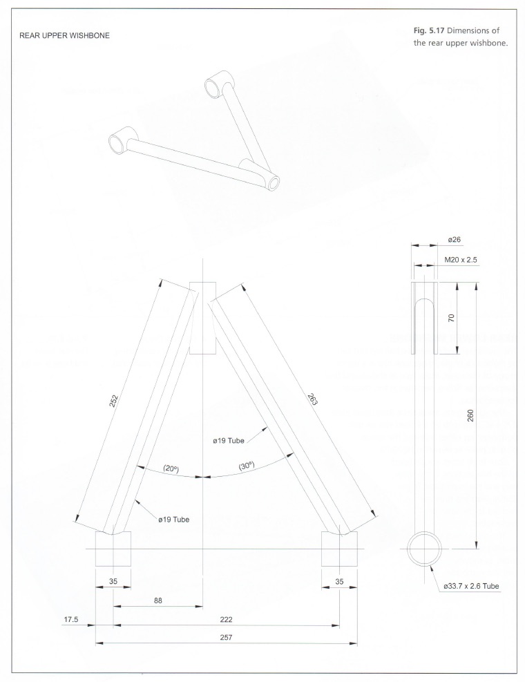
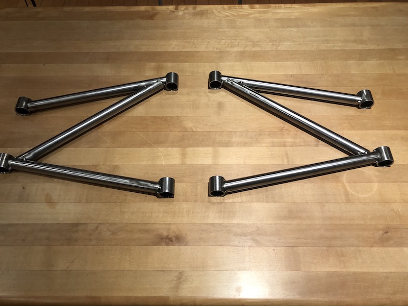
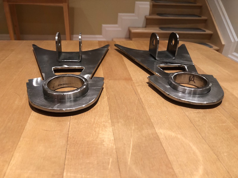
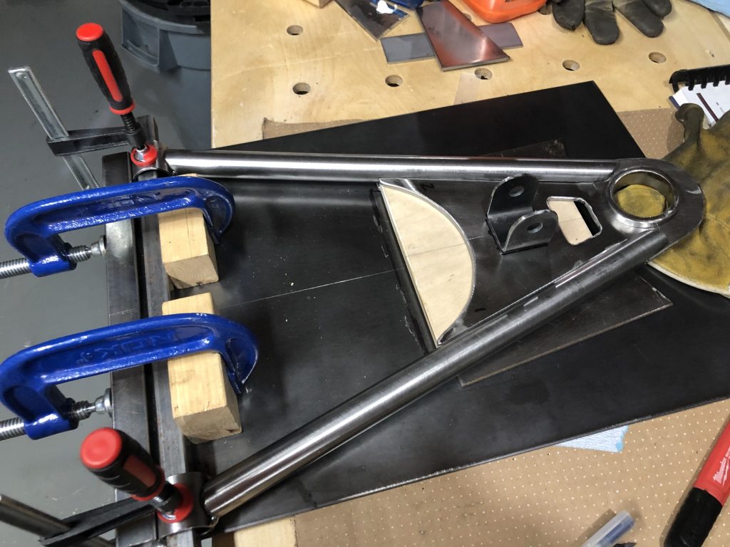
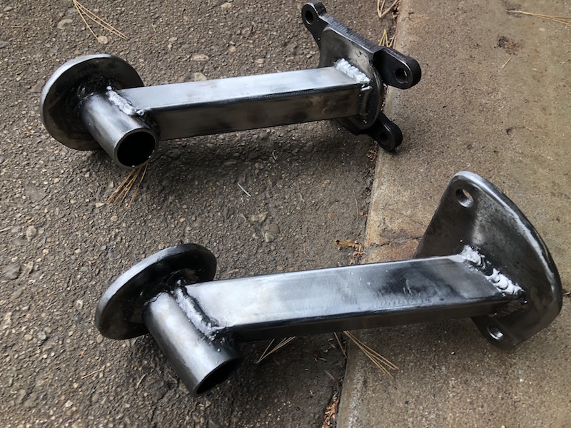
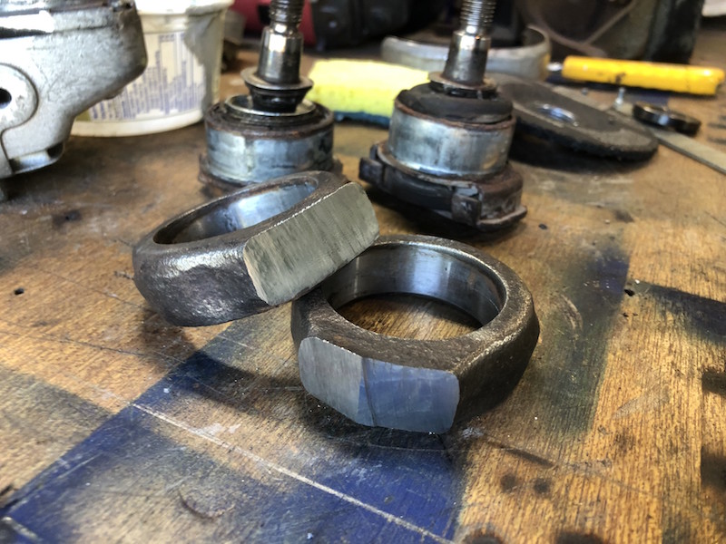
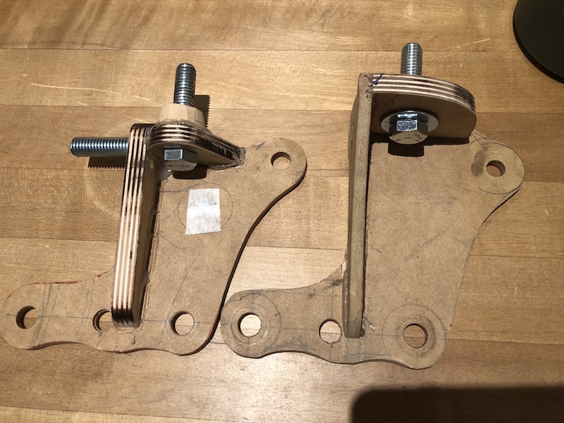
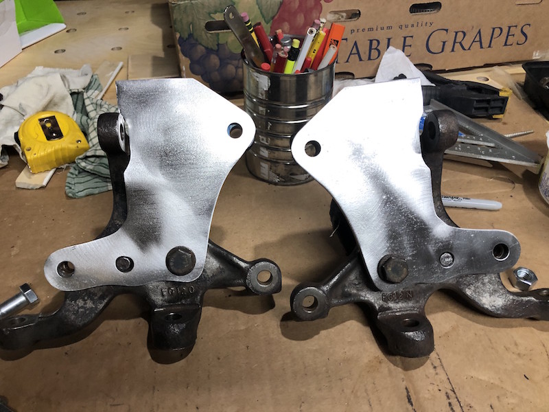
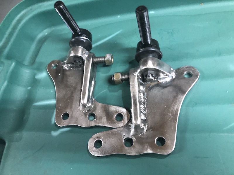
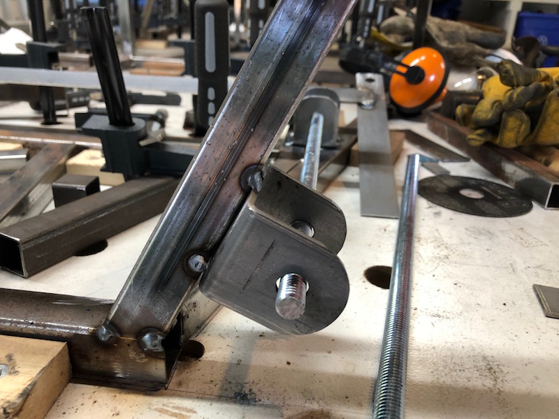
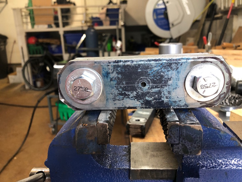
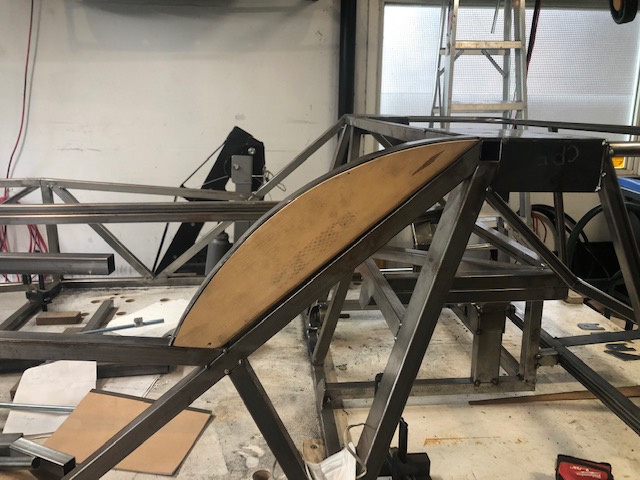
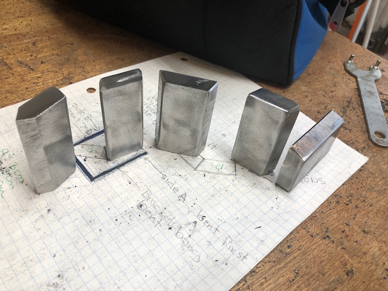
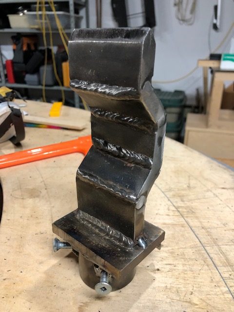
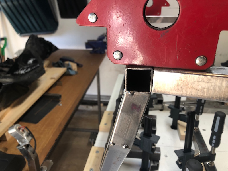
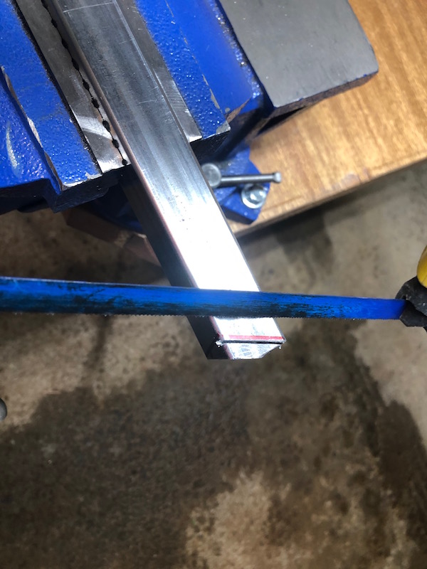
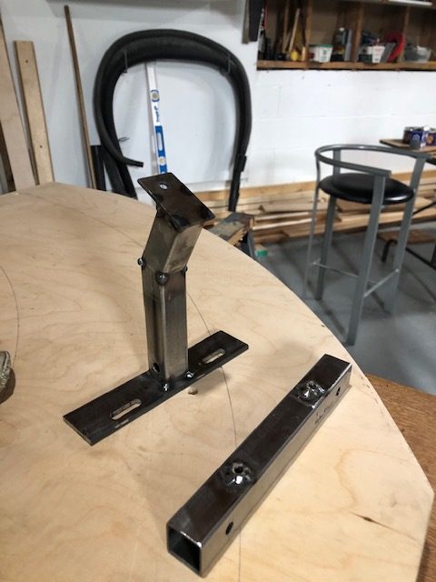
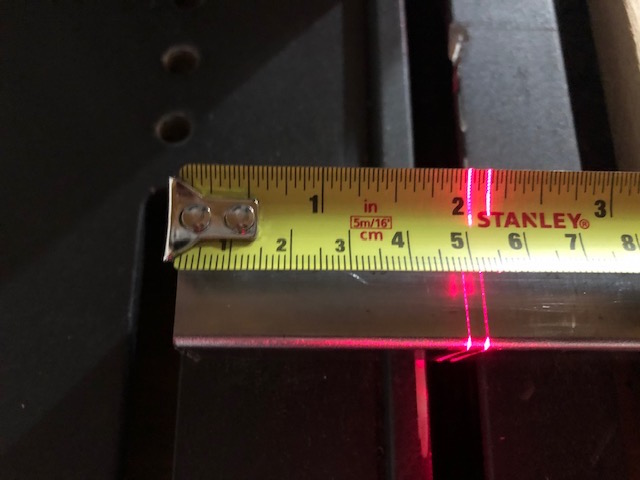
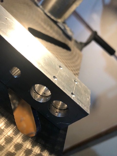
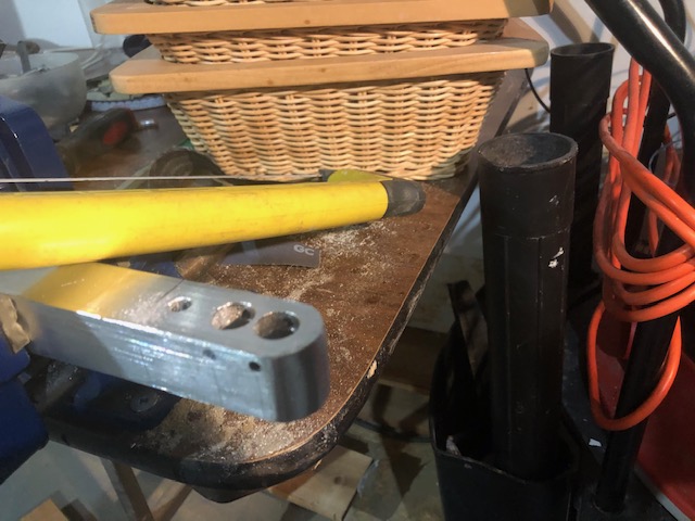
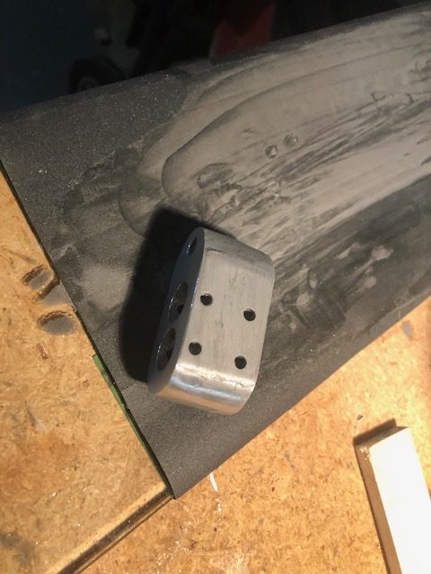
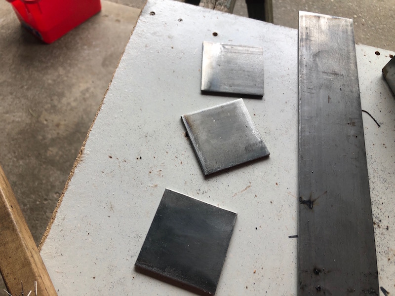
Each of the four control arms present different “learning opportunities”. These arms are not symmetrical, but they are flat so one jig can be used to create both the left and right parts. They just need to be flipped to orient them properly on either side. They also use a heavy threaded holder at the pointy end. A small fabricated assembly (threaded rod and bushing holder) threads into it and allowing camber adjustment of the rear wheels.
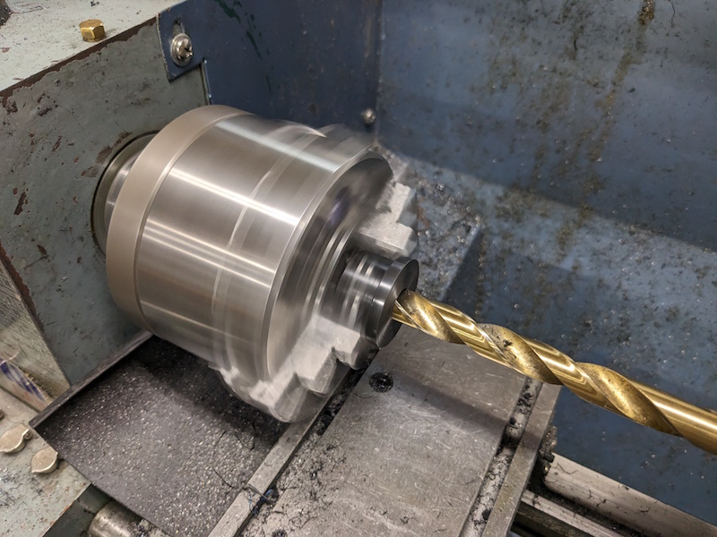
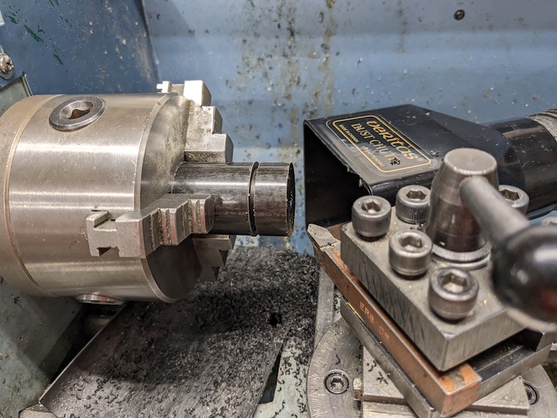
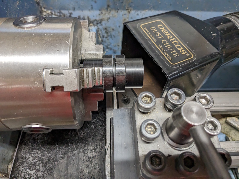
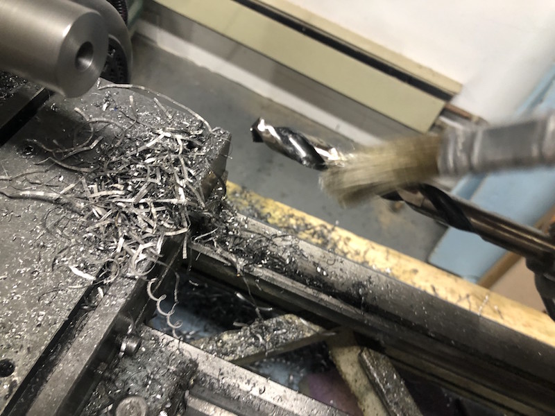
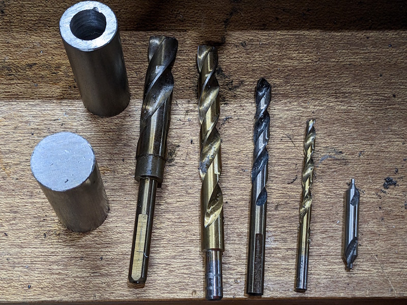
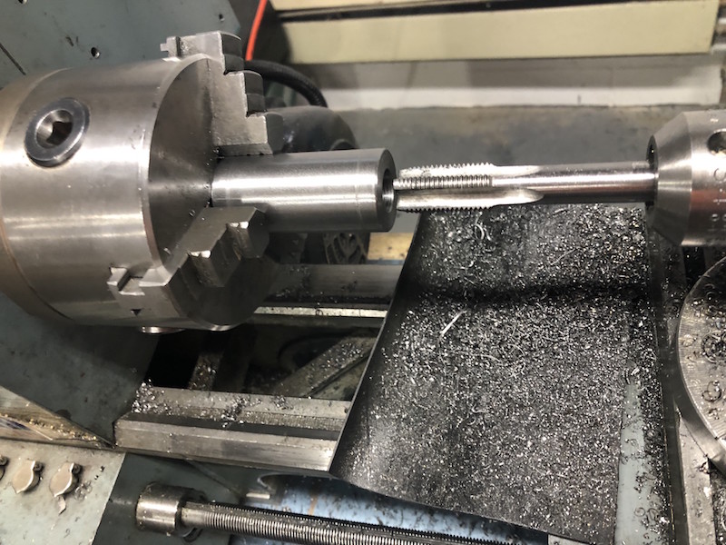
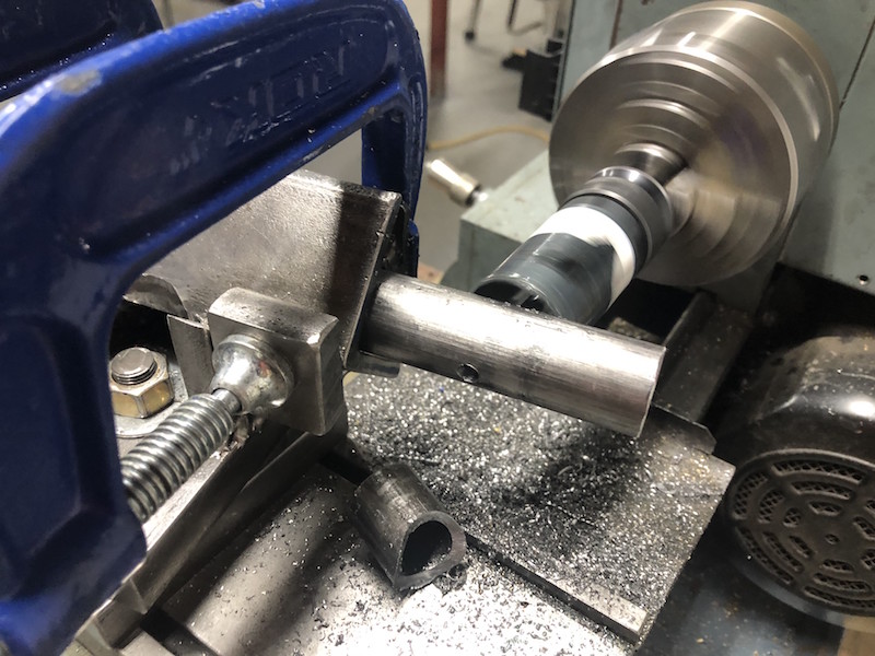
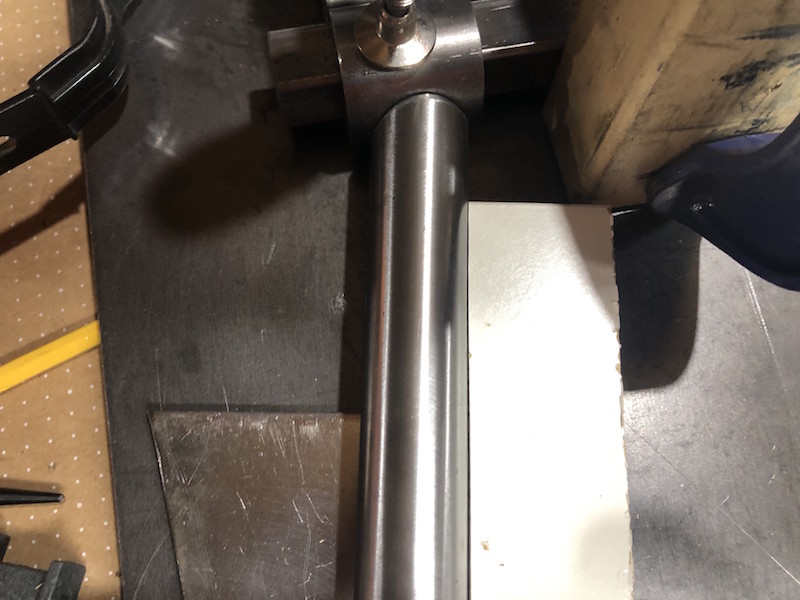
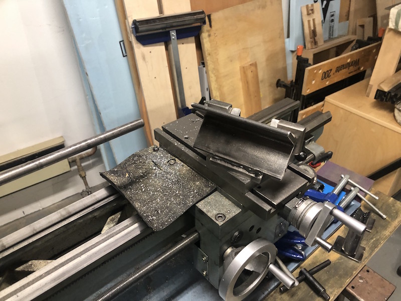
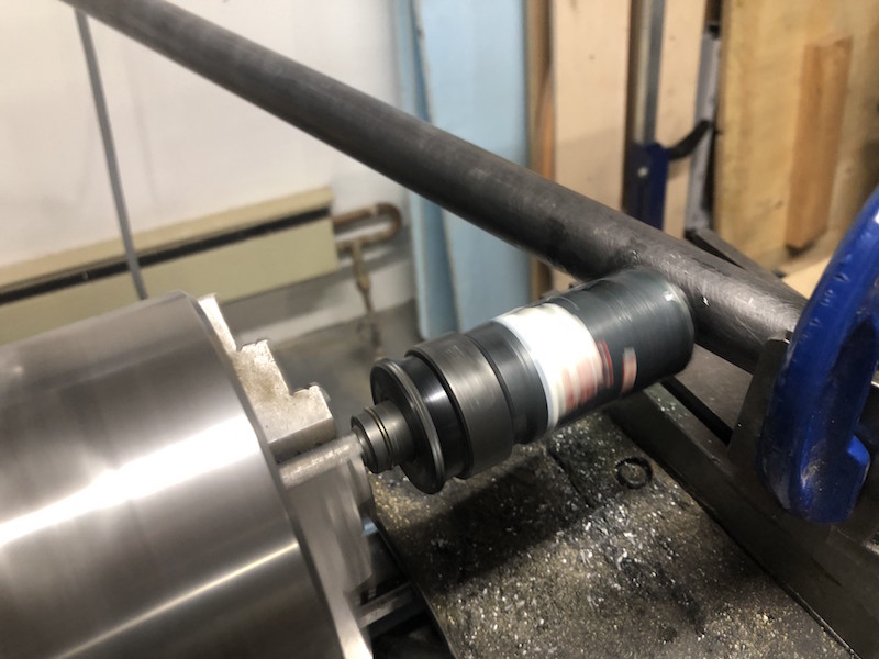
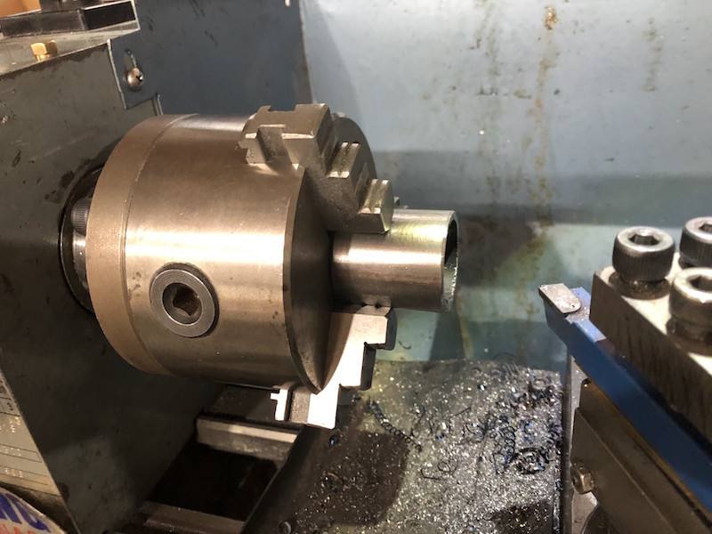
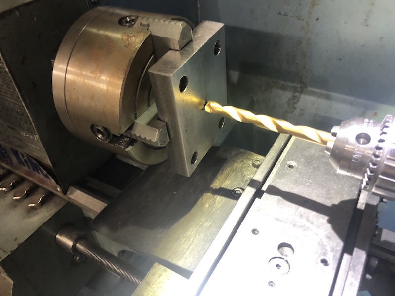
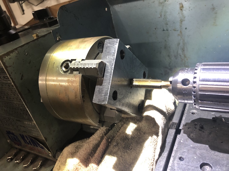
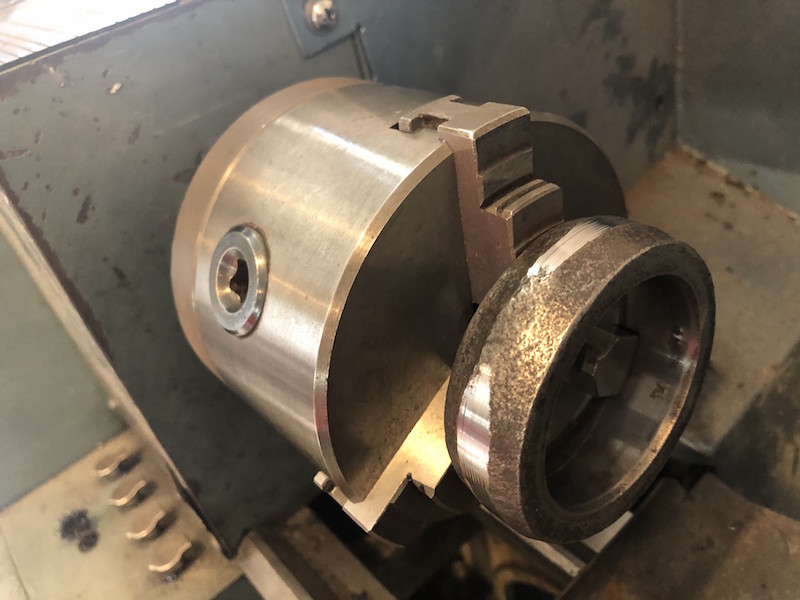
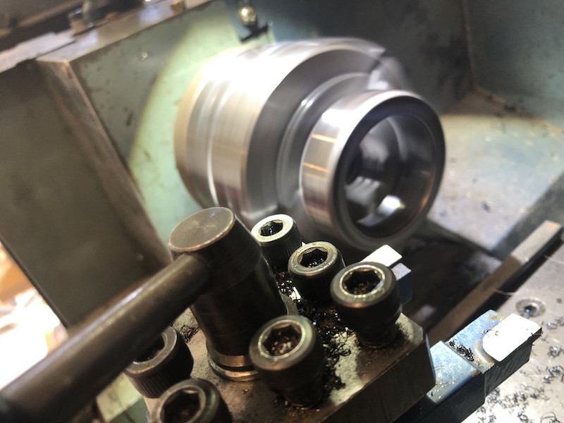
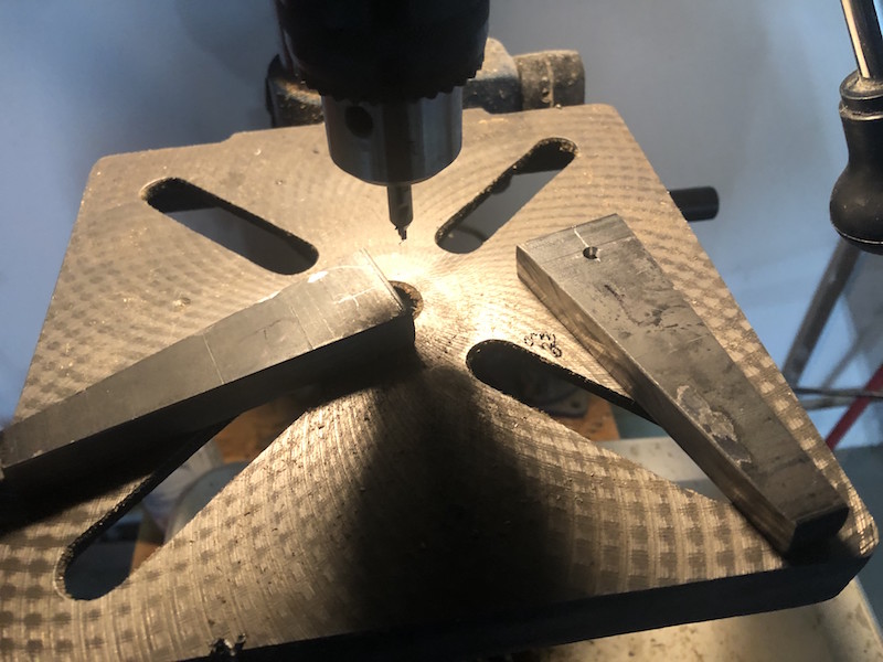
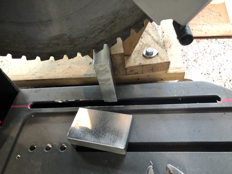
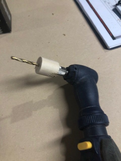
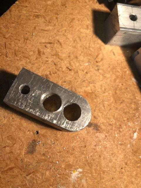
I started by making the heavy threaded holders for both these and the front upper control arms. About this time I realized I could not build this car without a lathe! The solid stock spins in the chuck and a drill bit on the tail stock (Jacobs chuck) is advanced into the work piece. The hole is drilled progressively starting with a center drill to establish the center and then working up to the the hole diameter required. Liberal amounts of cutting oil are brushed onto the bit to help cool it and aid in cutting.
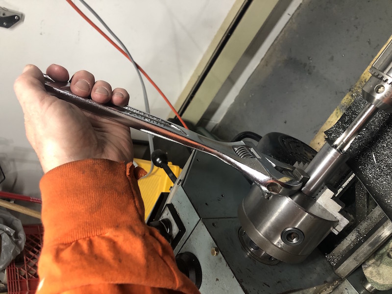
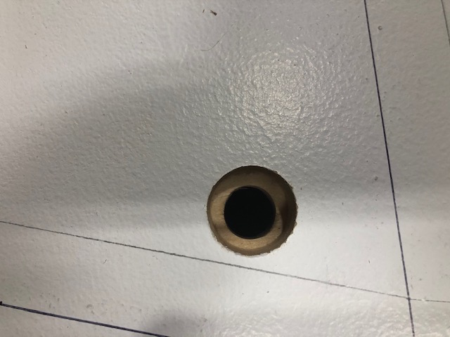
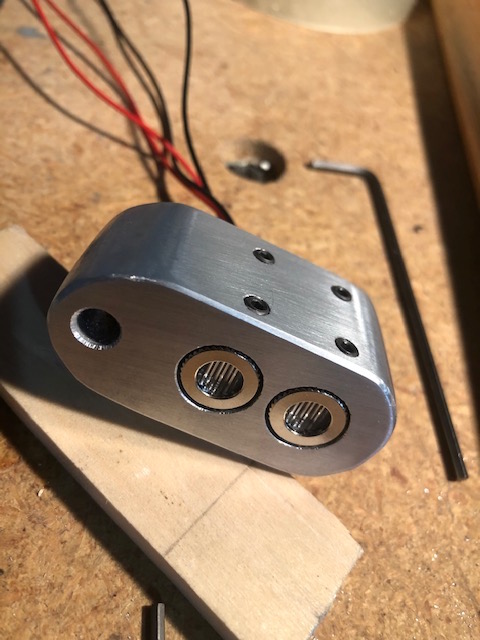
The lathe is also used to cut the thread in the hole. A crescent wrench was used to turn the chuck slipping onto the jaws of the 3 jaw chuck. This is slow work!
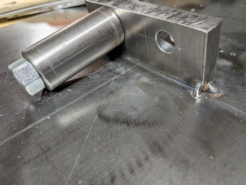
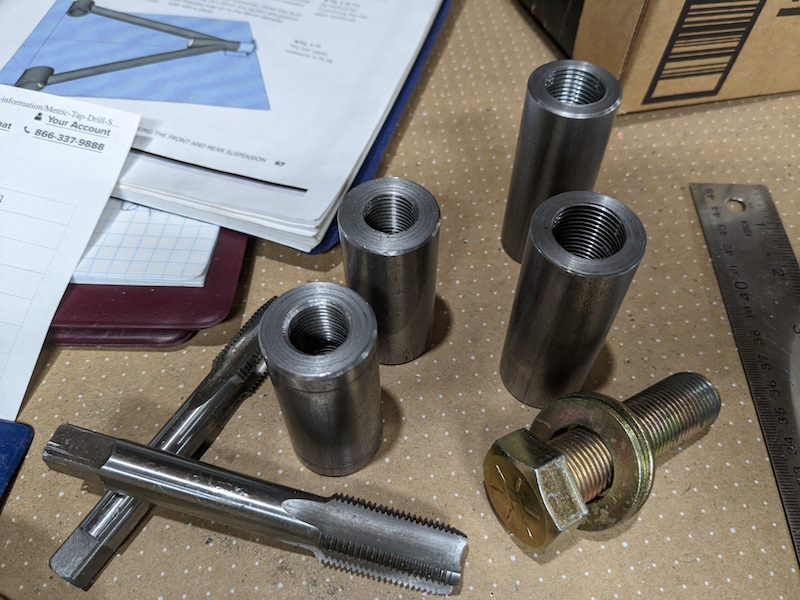
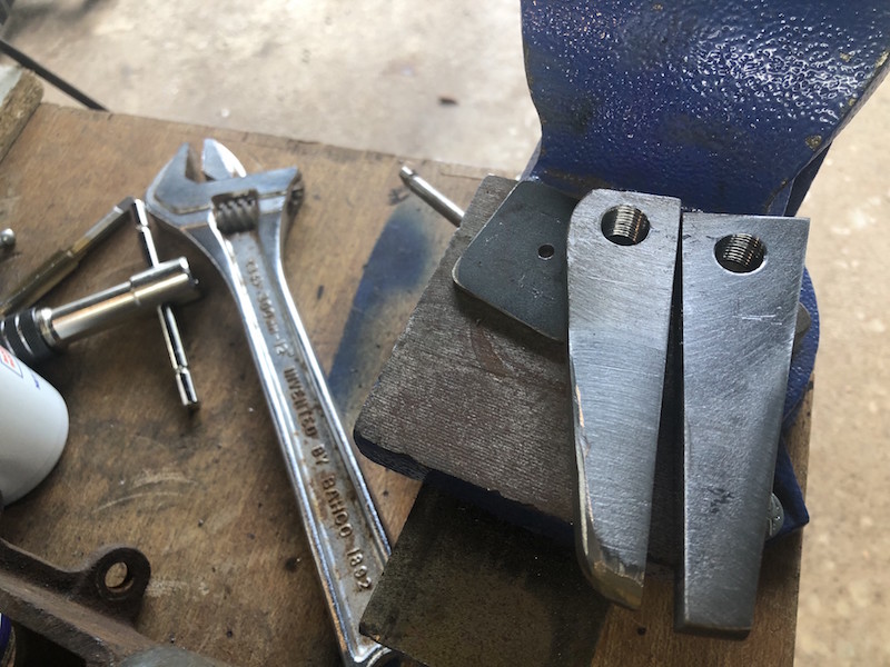
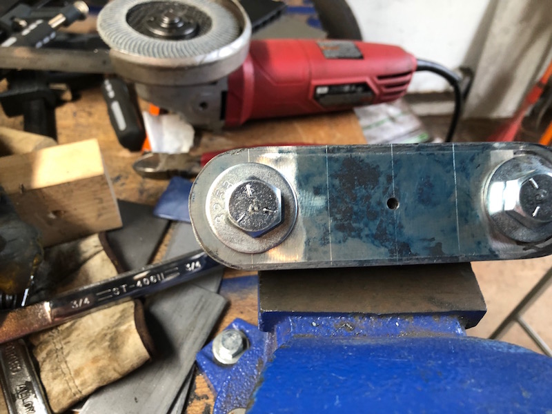
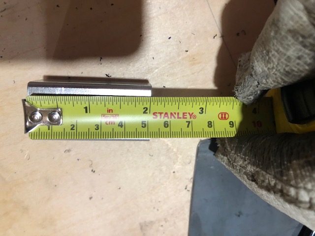
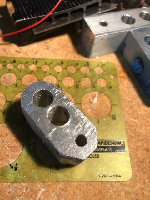
The front and rear threaded holders finished. The front pair are on the left.
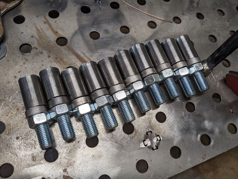
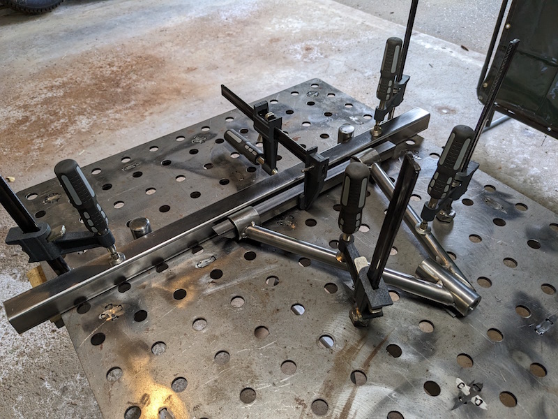
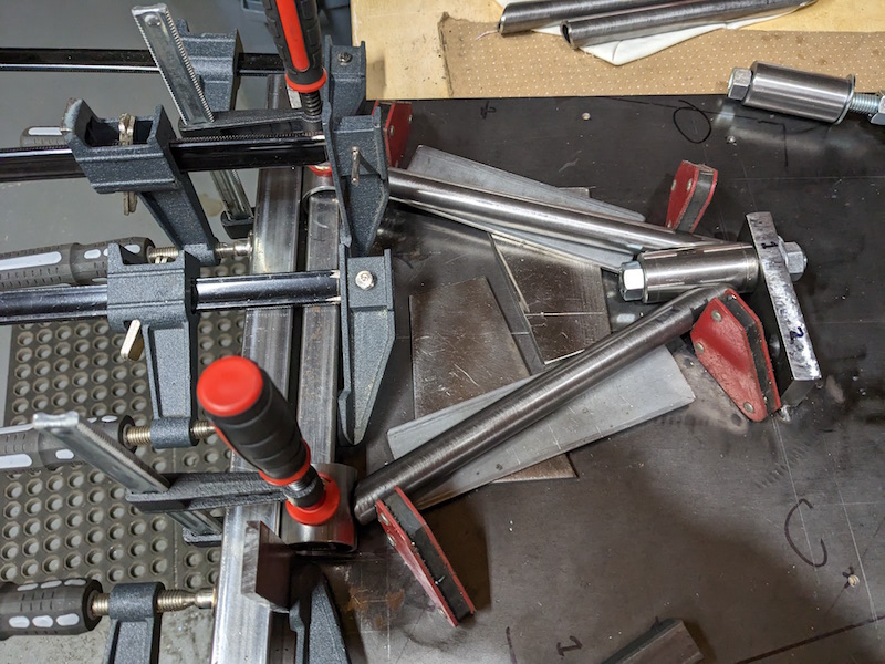
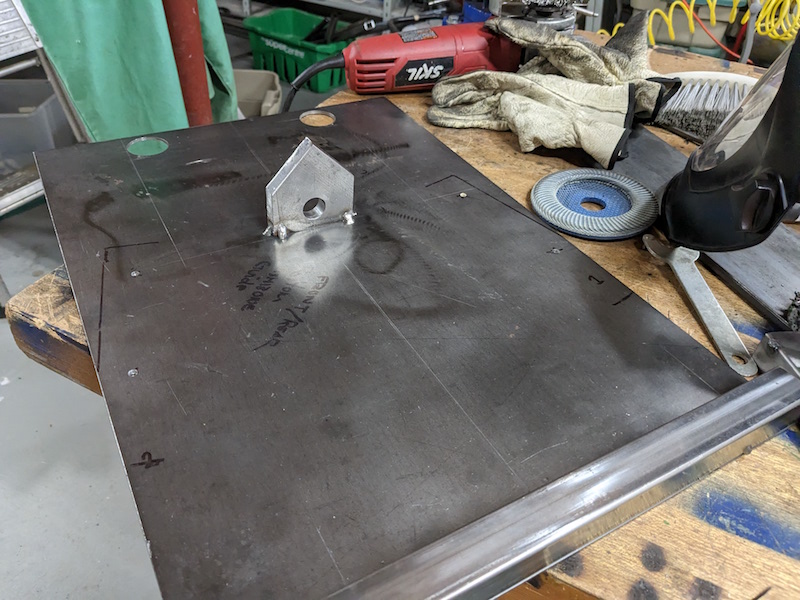
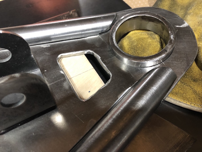
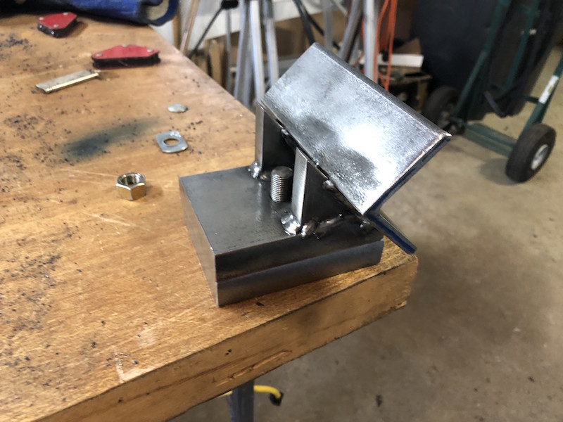
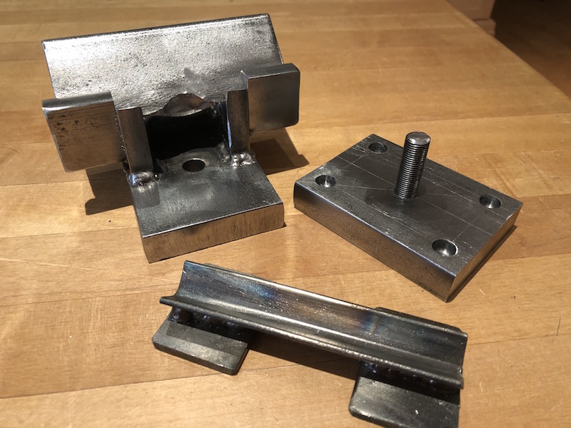
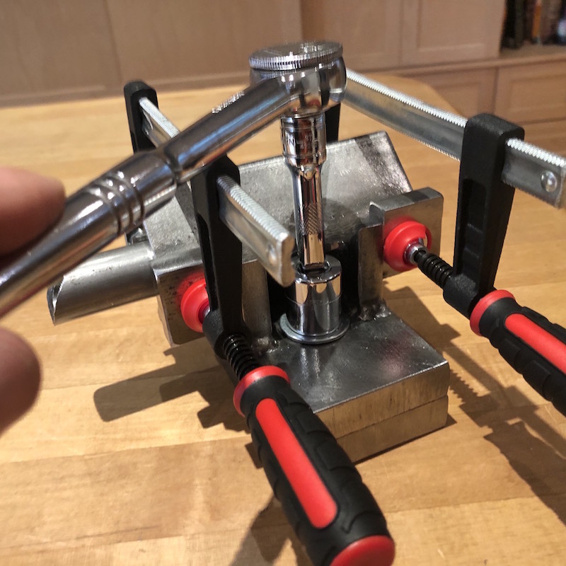
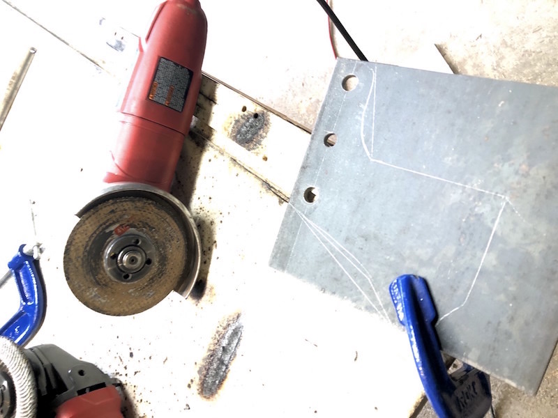
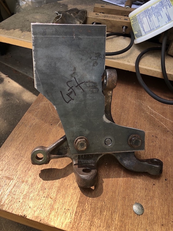
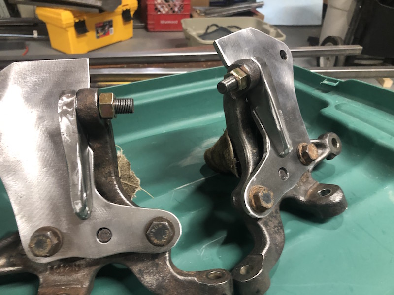
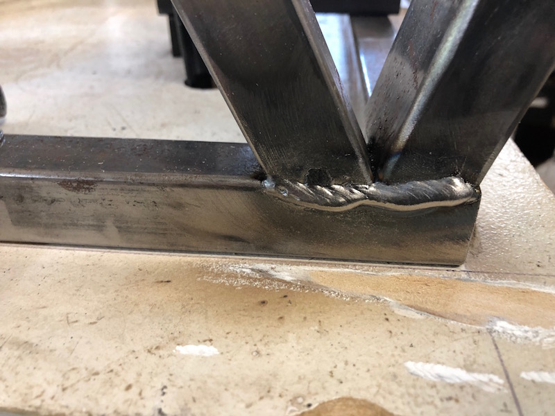
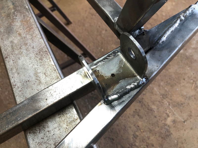
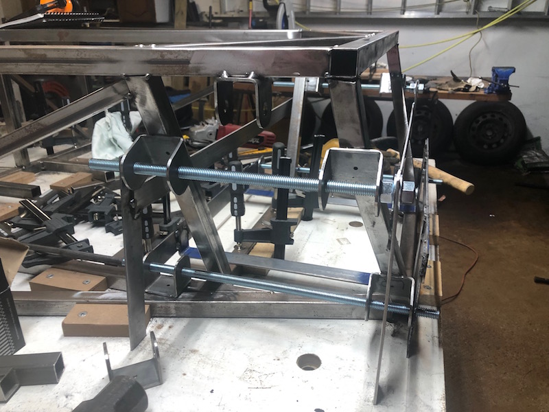
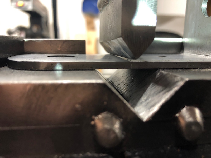
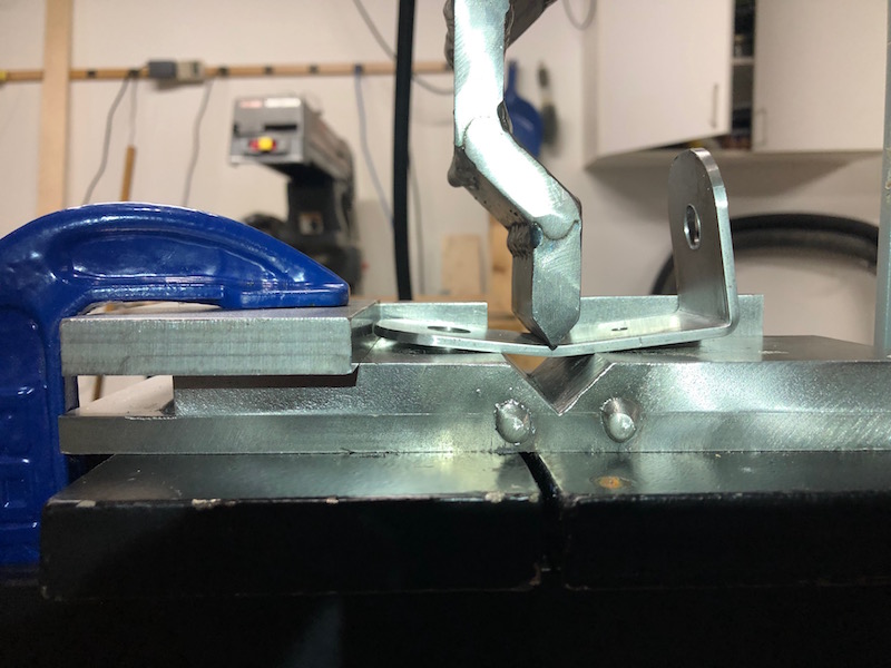
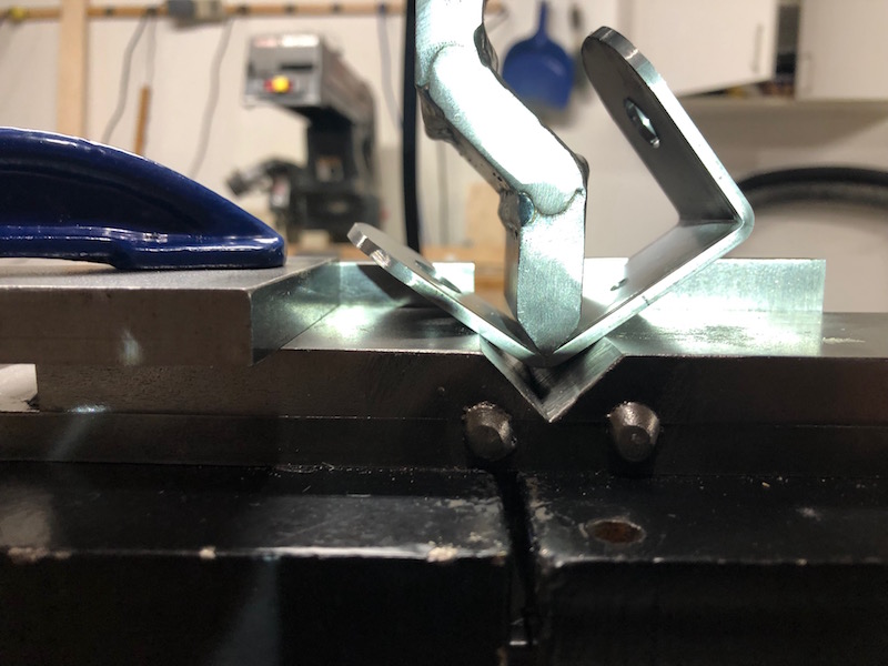
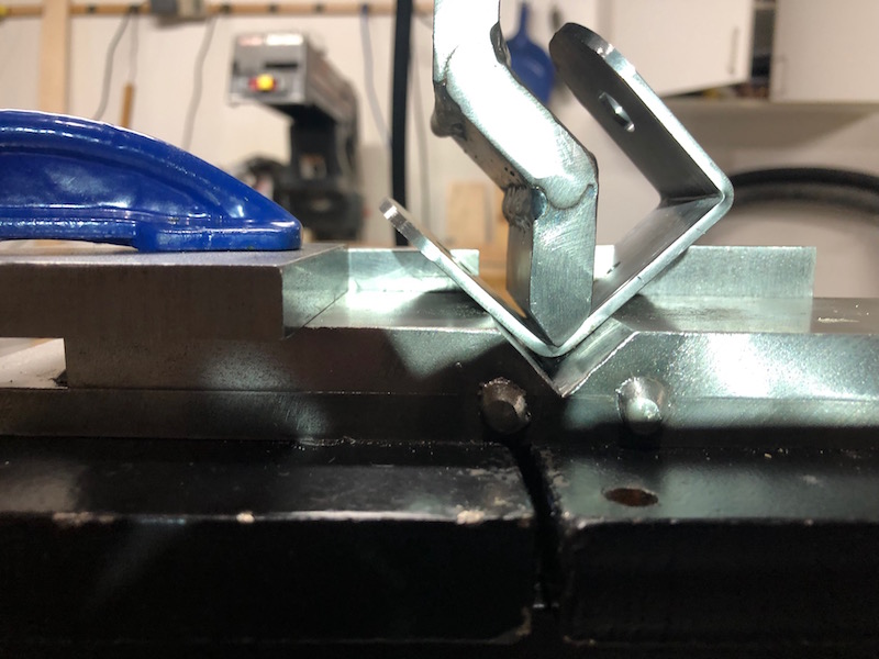
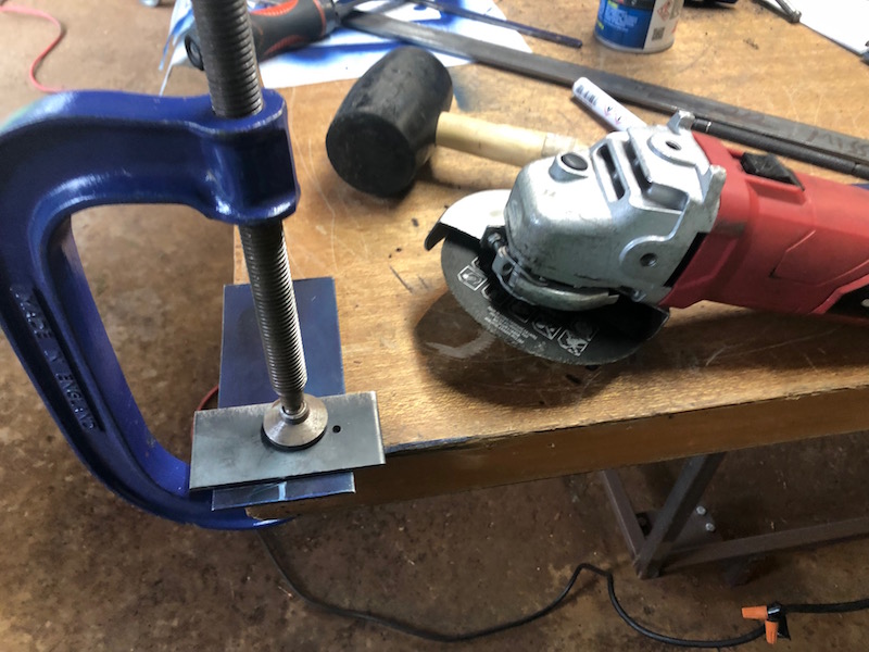
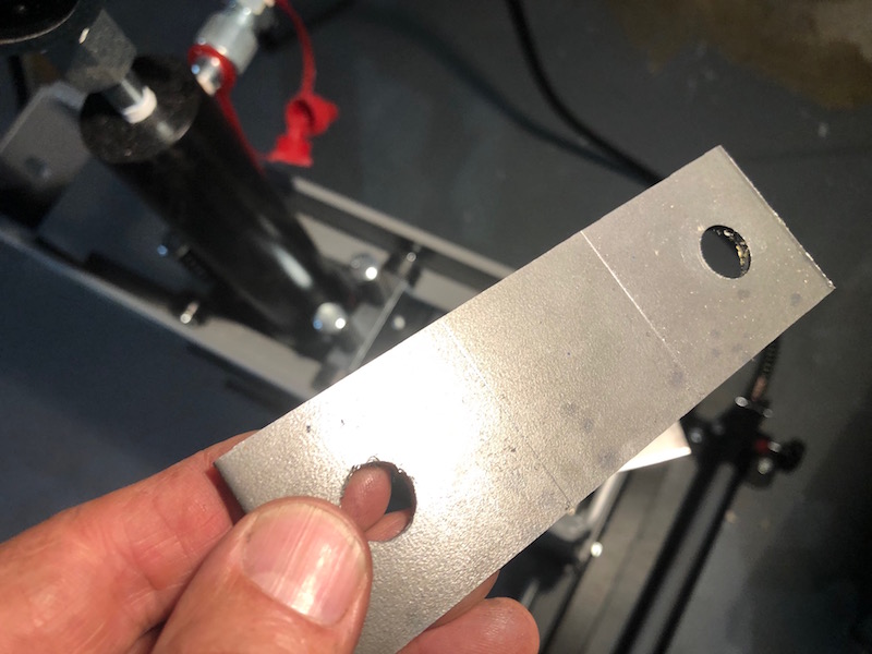
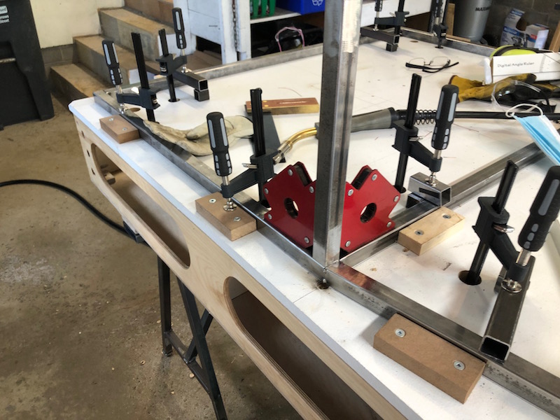
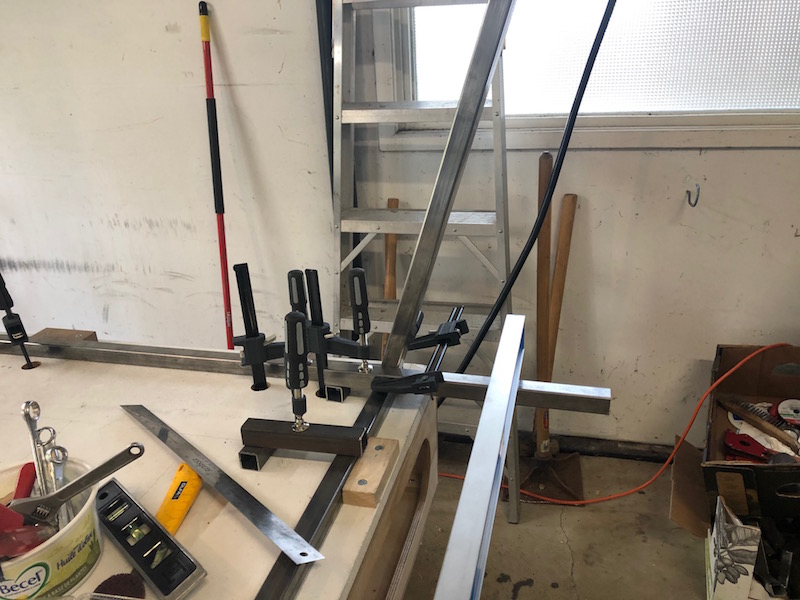
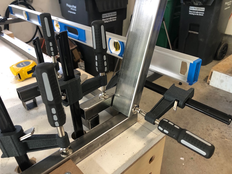
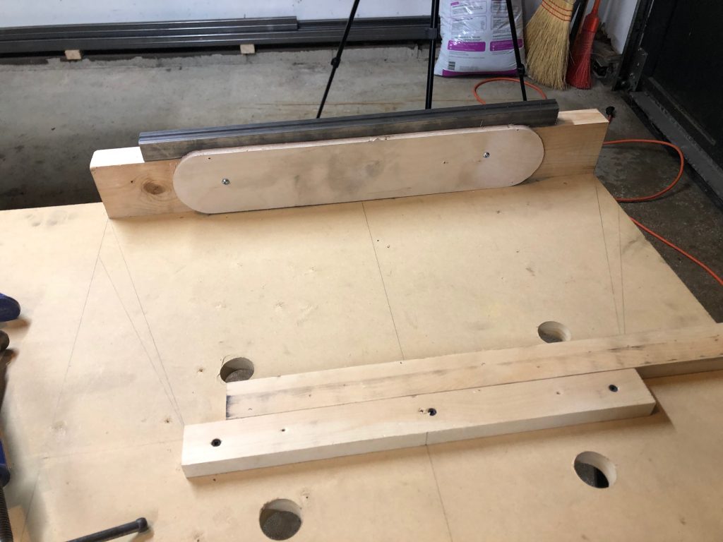
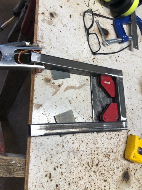
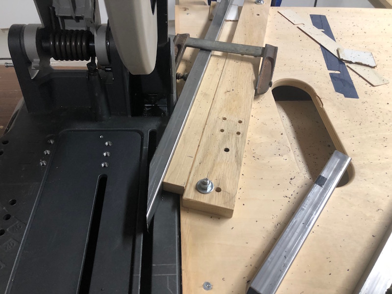
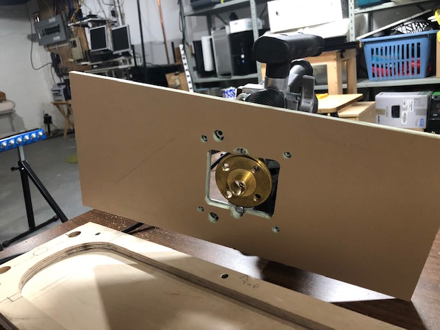
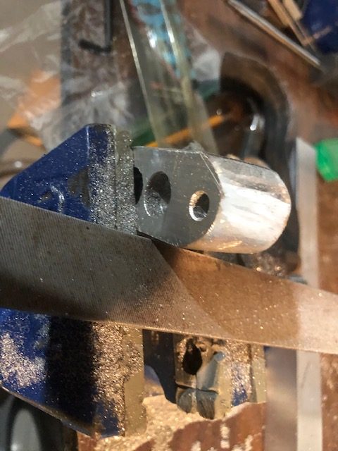
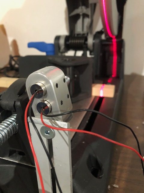
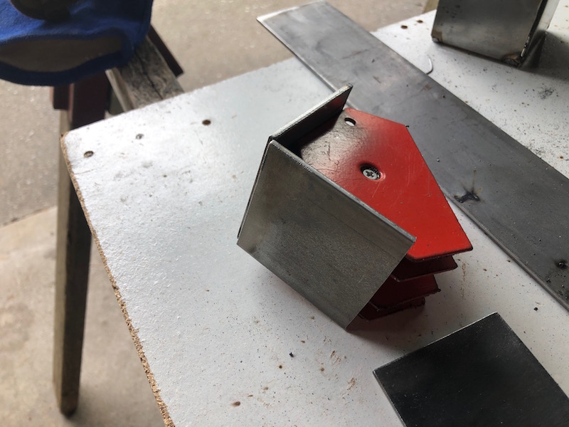
Another jig needs to be made up with a base tube to clamp the bushing tubes in position and a vertical plate (with a hole) to support the threaded holder. The holder can be bolted onto the vertical plate (made out of a random shape piece of steel if you are curious) to hold it solidly in position.
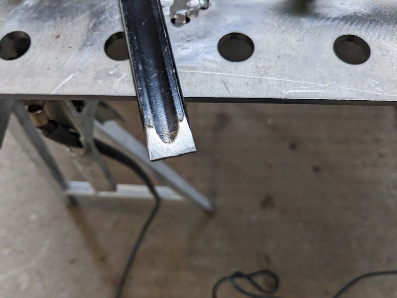
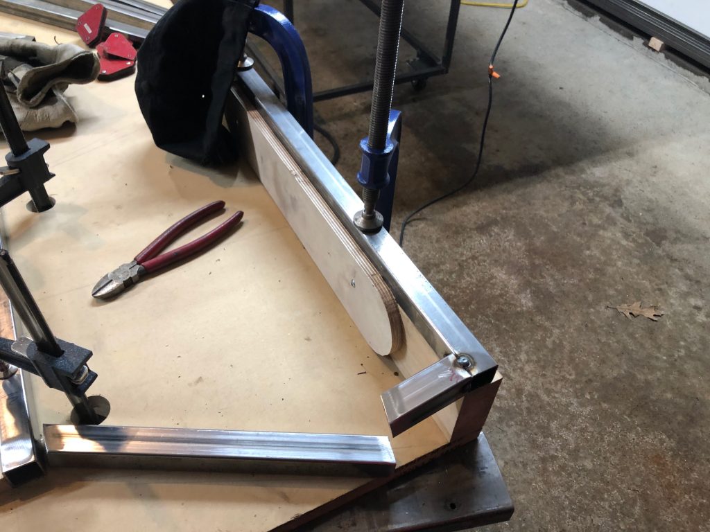
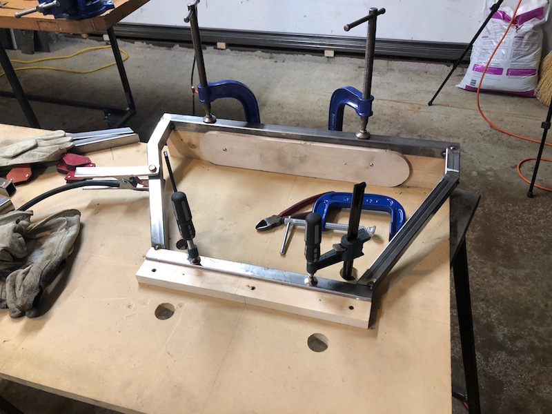
Tubes were prepped, notched and touched up before getting a good fit. I used several welding magnets to hold the tubes in position for tacking. Again, scrap plate was used to support the tubes at the appropriate height.
Next on the hit list are the lower control arms for the back end.
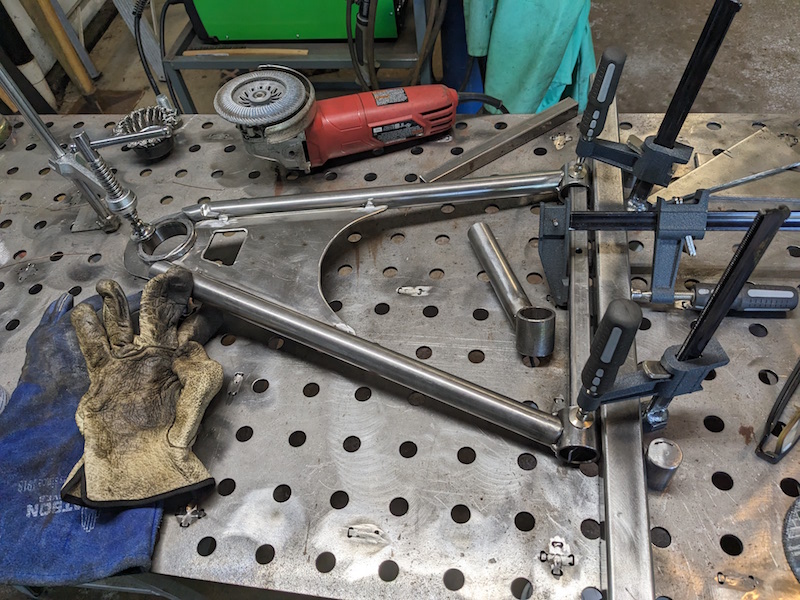
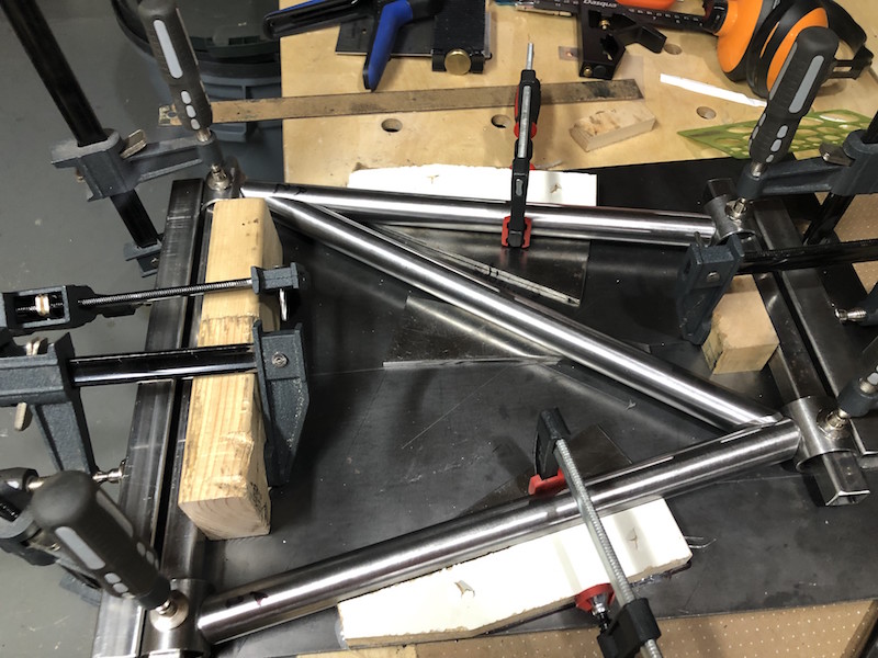
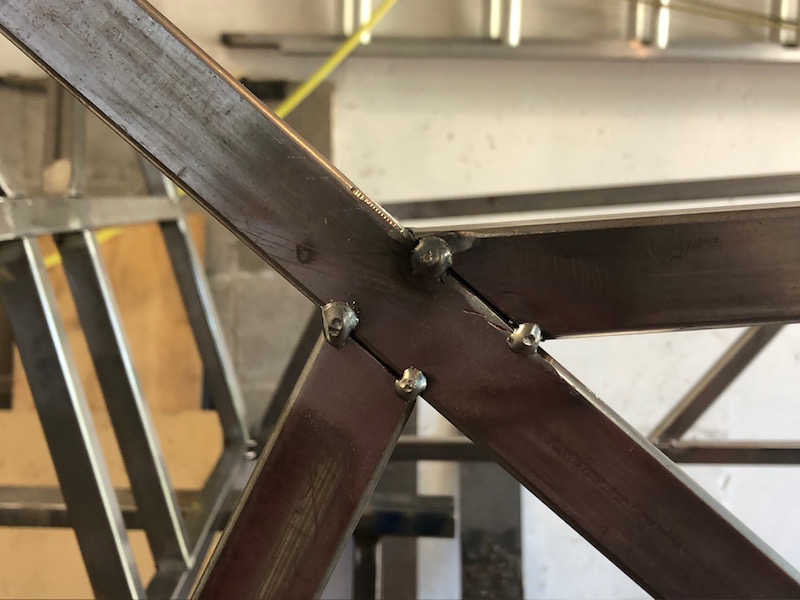
Hey these look pretty complicated too! Some funny intersecting angles and lots of notching required.
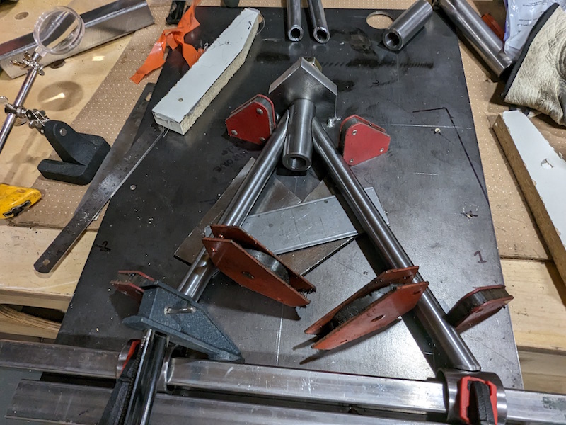
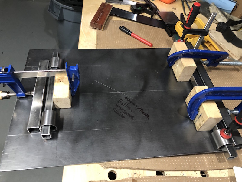
Again we use a jig to ensure that everything gets lined up properly. Here I have the 4 bushing tubes clamped in place, now I just need to make the zig-zaggy tubes.
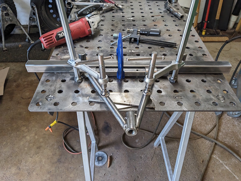
The first order of business is to notch all the outer tubes. They have bushing tubes on both ends and are pretty straight forward to notch.
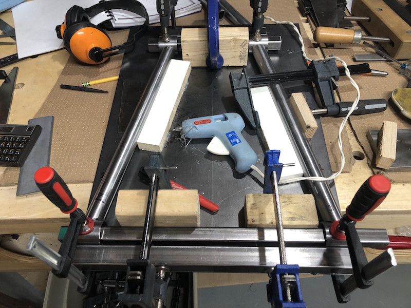
I hot glued a couple particle core strips down to align the outer tubes.
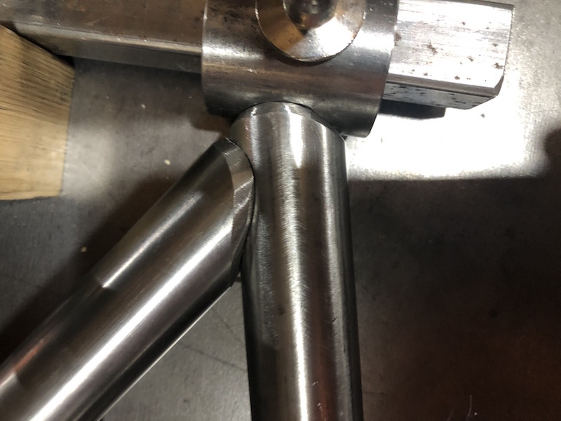
Both ends of the are fitting nicely. I’m using scrap 3/16″ plate to space the tube up off the jig as it is smaller diameter than the bushing tubes.
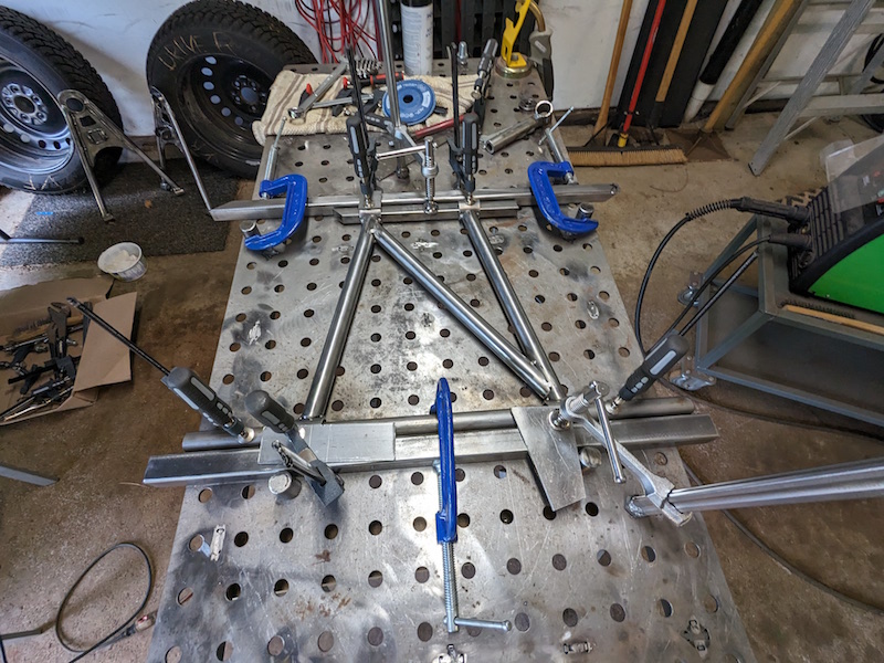
Cutting the acute angles for the cross brace was challenging. The cut was so long that the waste piece inside the hole saw was bottoming out. I had to back the tube out, cut off the waste piece with the angle grinder, and reengage the work piece to finish the cut. The results were very good.
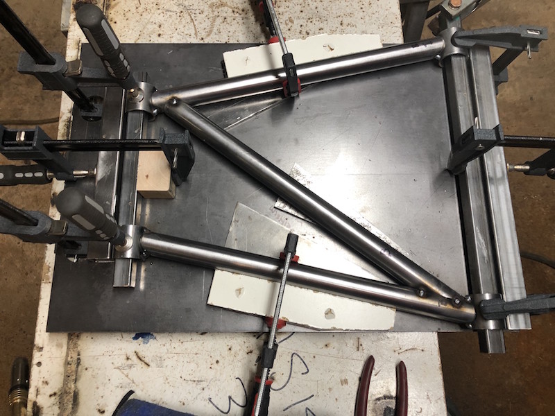
I relocated the particle core guides to the outside of the tubes because they were interfering with the diagonal brace (of course). Things are fitting very well!
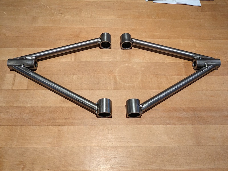
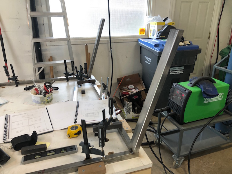
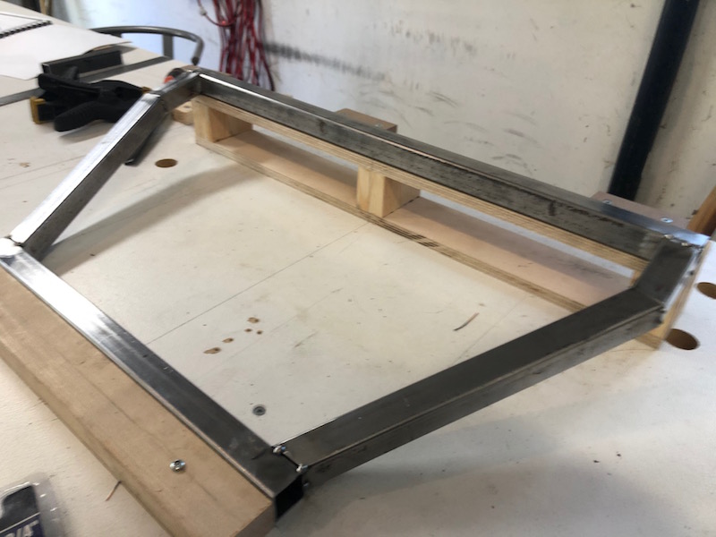
A trip to the welding shop and everything is tacked together. I will wait till I have all of the control arms tacked together before fully welding them. I need more time to get my nerve up LOL.
I am starting with the lower front control arms. These are arguably the most complex of all the control arms but they do have the simplest tube to tube joints (only the bushing tubes) and since I am new to tube notching I decided to start with them.
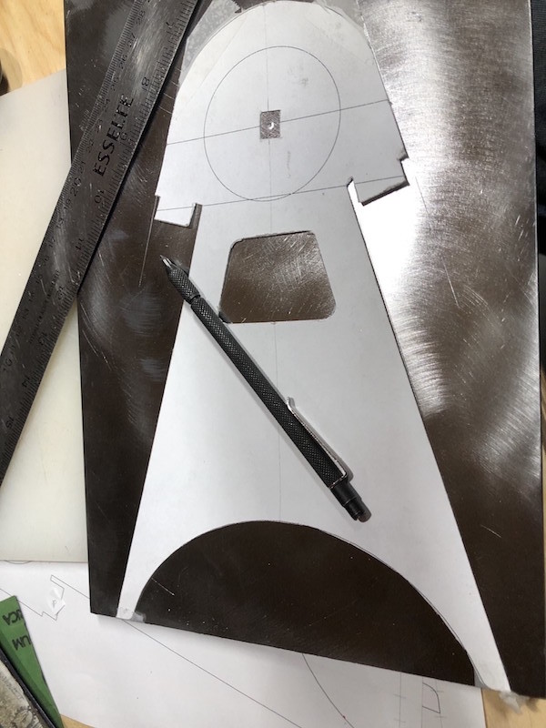
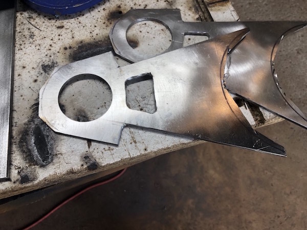
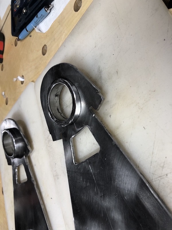
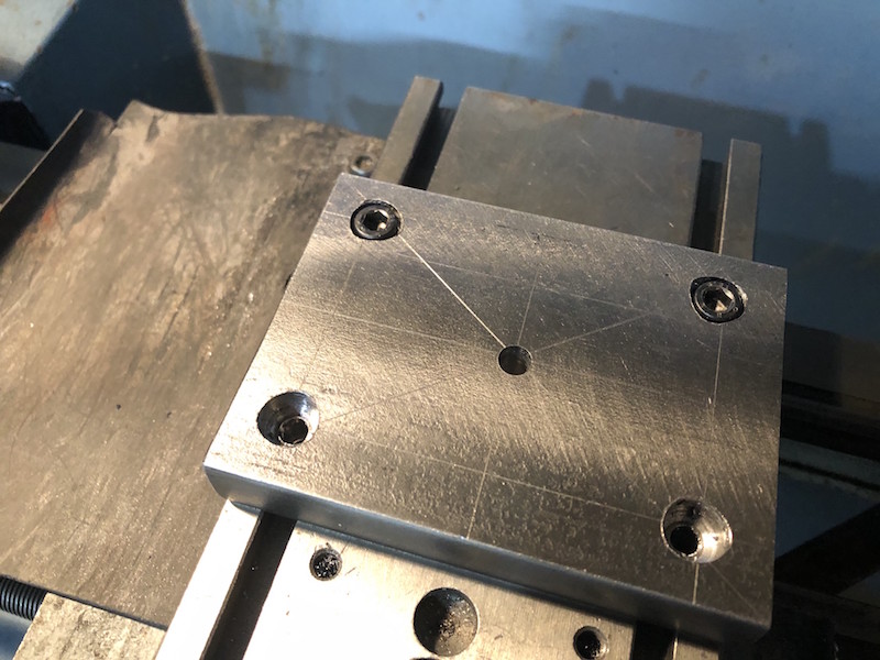
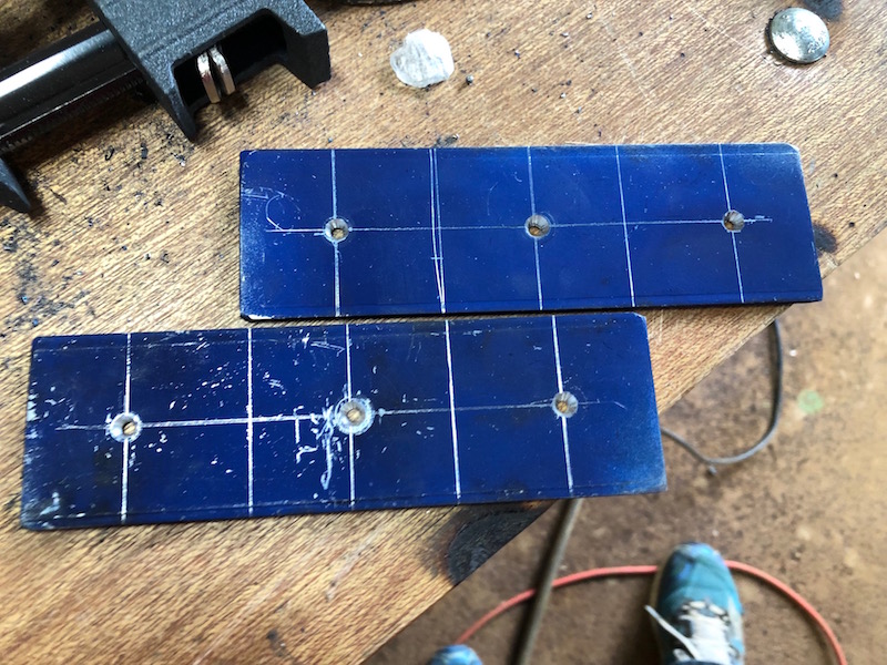
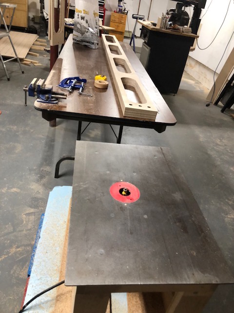
The doner car from the book uses a bolt in ball joint while the BMW has a pressed in ball joint. I have modified the web plate lengthening the nose of to accommodate the holders that were machined on the New Brunswick trip. The center of the ball joint remains the same as the drawing above. I used a paper template to trace out the shape on the steel plate.
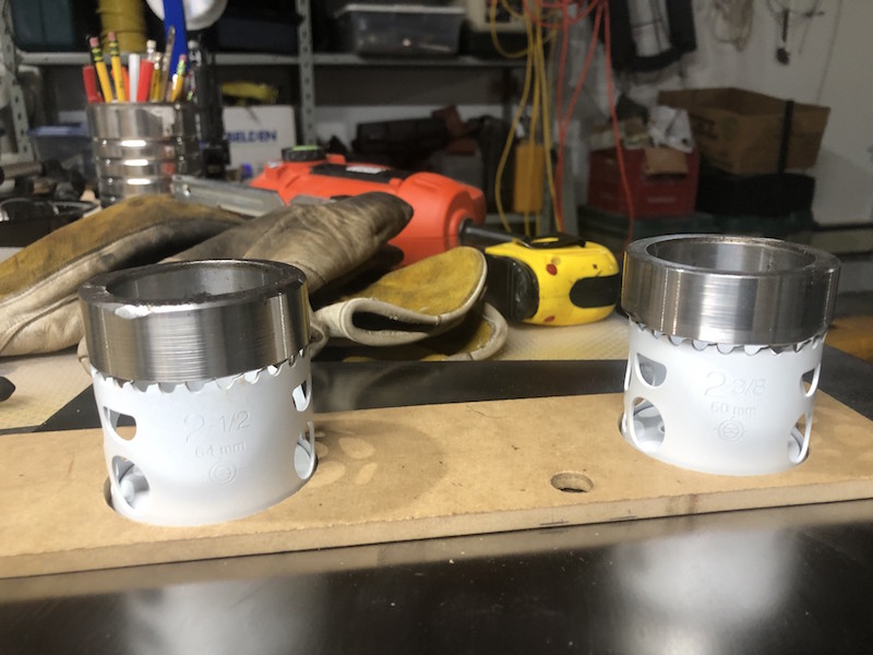
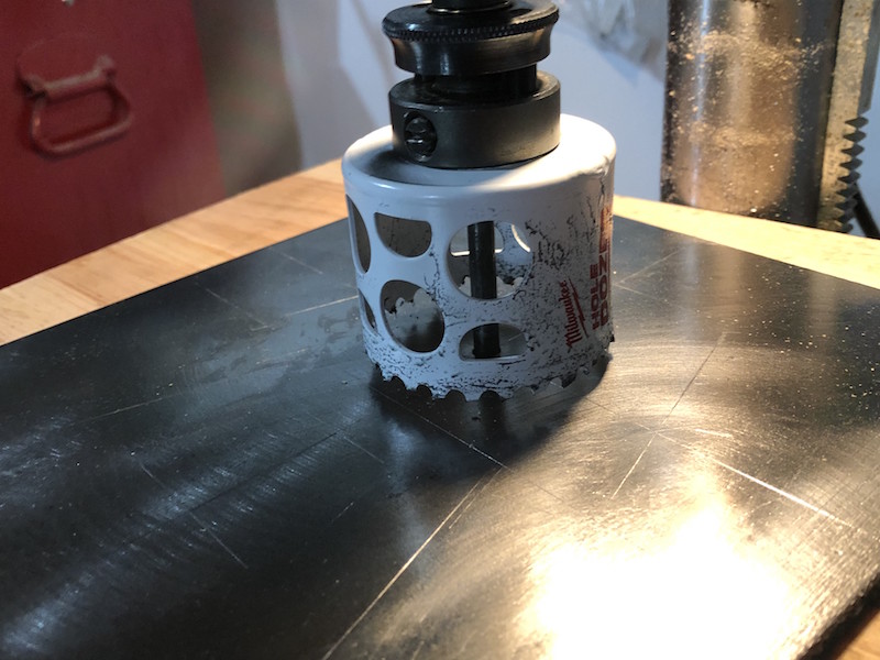
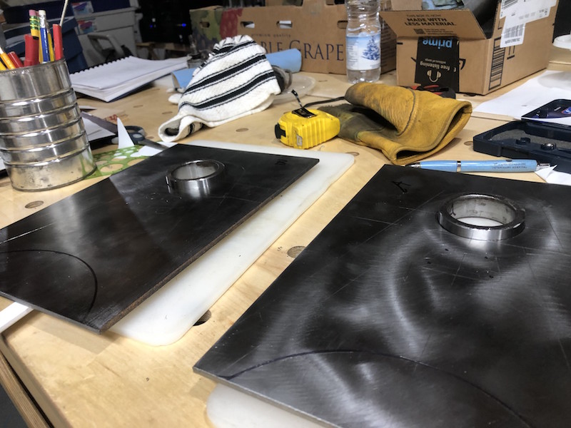
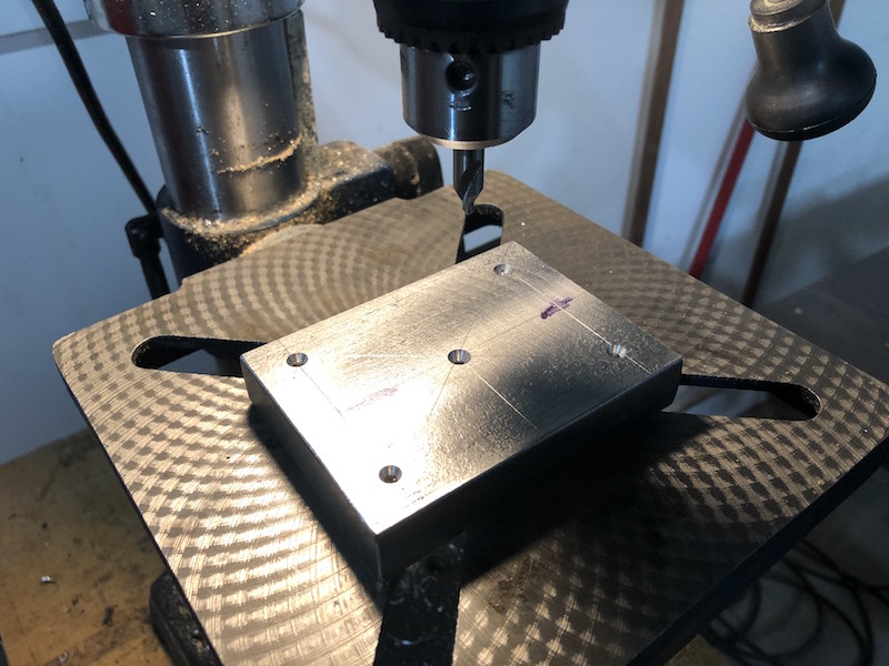
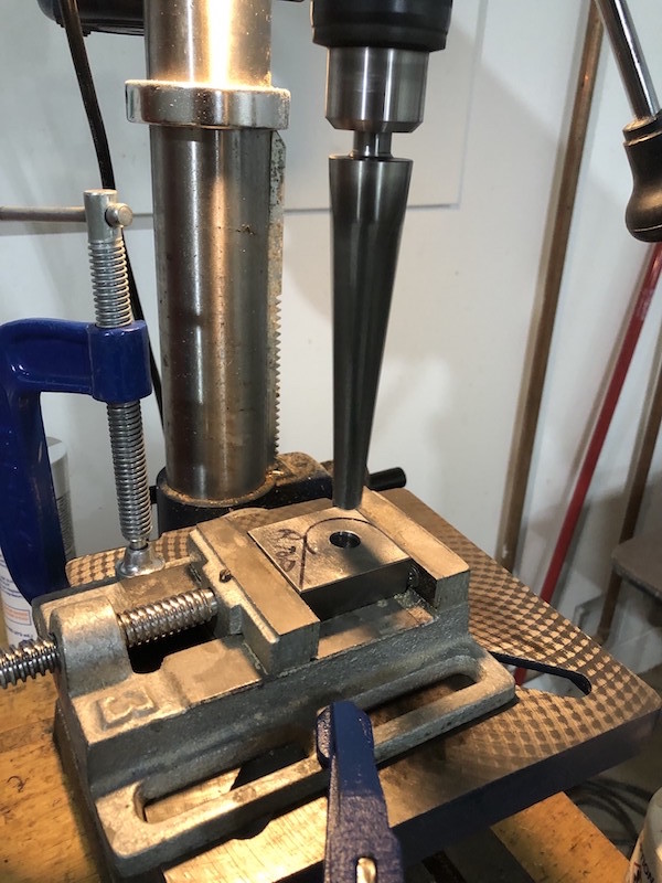
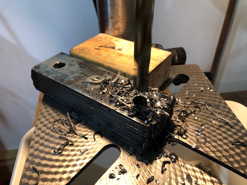
Step one was to drill the holes for the ball joint holders. I used a a hole saw that was slightly smaller than the outside diameter of the ball joint holder.
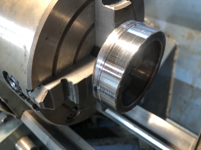
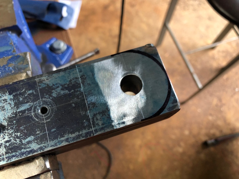
I then used the lathe to turn down the holders leaving a small shoulder that would help position the holder height in the web plate.
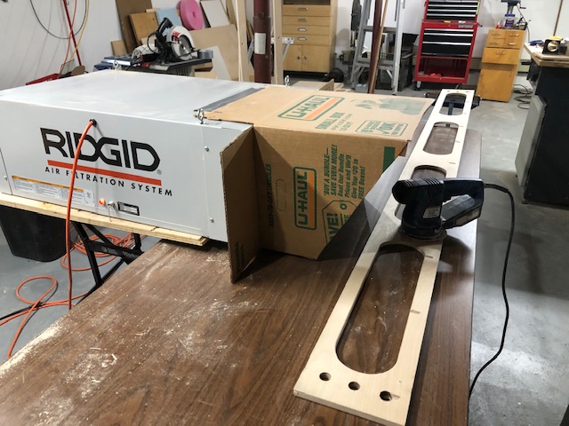
After much cutting and grinding the plates are done. I named my angle grinder CNC.
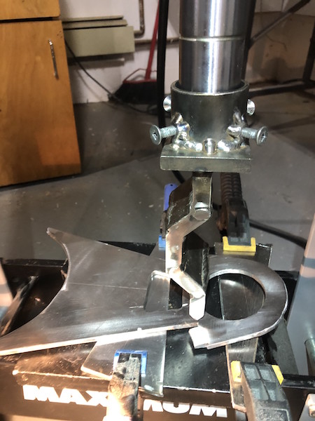
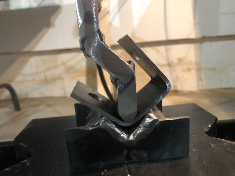
The plates required a 10 degree bend on the head end, that was achieved with the hydraulic press.
Time to notch some tubes to go with those web plates. By cutting a double length piece in the center I get two identical notches and cut my work in half. Win Win!
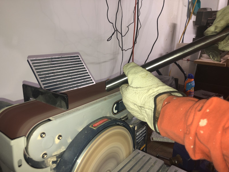
After notching any burrs get cleaned up and the edge of the notch gets beveled on a belt sander, this will create a better connection when welded.
The 4 tubes for the front lower control arms beveled and ready for the bushing tubes. I also cleaned the inside of the tubes using some acetone and a cleaning “rod” powered by my drill. This got rid of any metal particles in the tube and hopefully any oil or contaminants from the manufacturing process. Contaminants inside the tube could affect the quality of the weld.
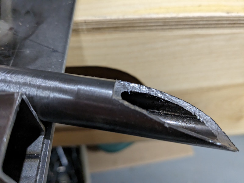
I tack welded the bushing tubes onto the notches and then split the other end of the tubes. I had decided to extend the tubes beyond the tongue that was left on the web plate and the tubes needed to be pass over the top and bottom of the plate.
A jig is used to align all the parts so that they can be tacked together. Here you can see the fit of the extended tubes (compared to the opening drawing) and the detail of the split end.
A chilly trip to the garage and the lower control arms are tack welded.
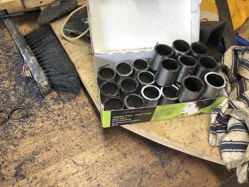
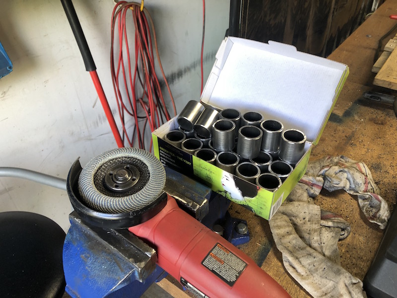
Time to start on the suspension control arms. Before we get too far into it we are going to need to make a bunch of bushing tubes as they are common to all the control arms. These short tubes are welded to the ends of the control arms, have bushings pressed into them and provide the pivot points for the suspension arms to swing.
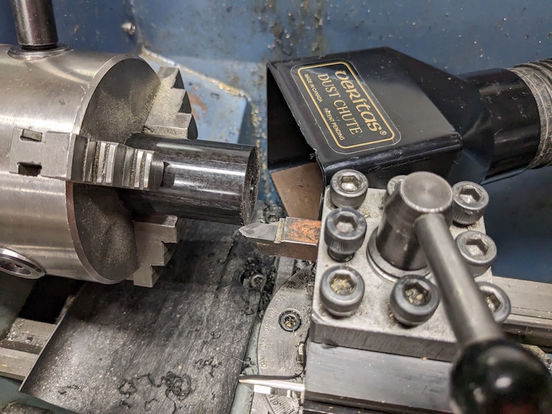
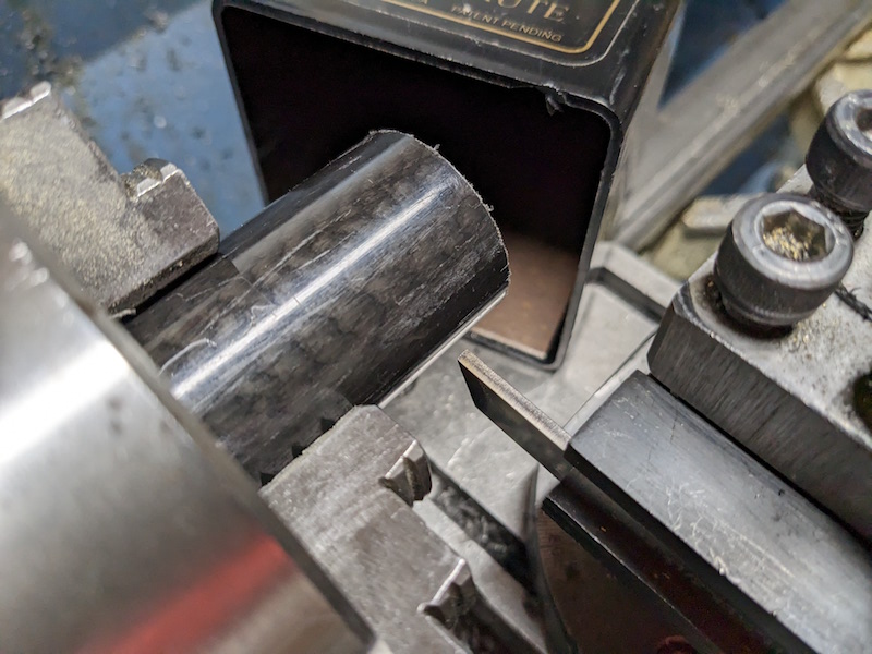
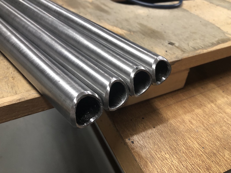
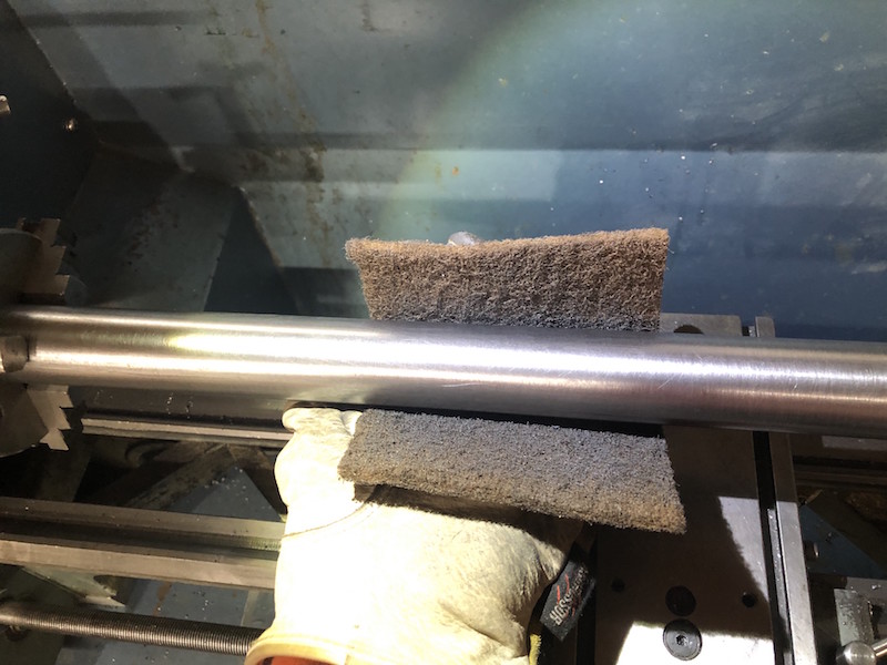
Lengths of 1-3/8″ DOM tubing (1/8″ thick wall) are cleaned using the lathe and a brillo pad. It is a lot easier and less work to clean the whole tube than try to clean the individual bits later.
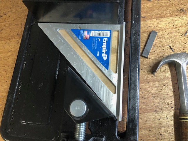
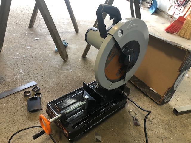
The chop saw is used to cut the tubes to length (about 1-3/8″ long), it does a good job but a bit of a clean up is required.
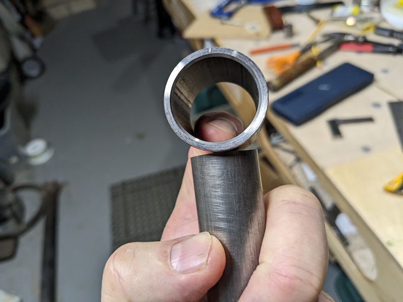
A flapper disk removes the large burs and then I used the lathe to lightly face the tubes and and make a small bevel to the inside edge of each piece.
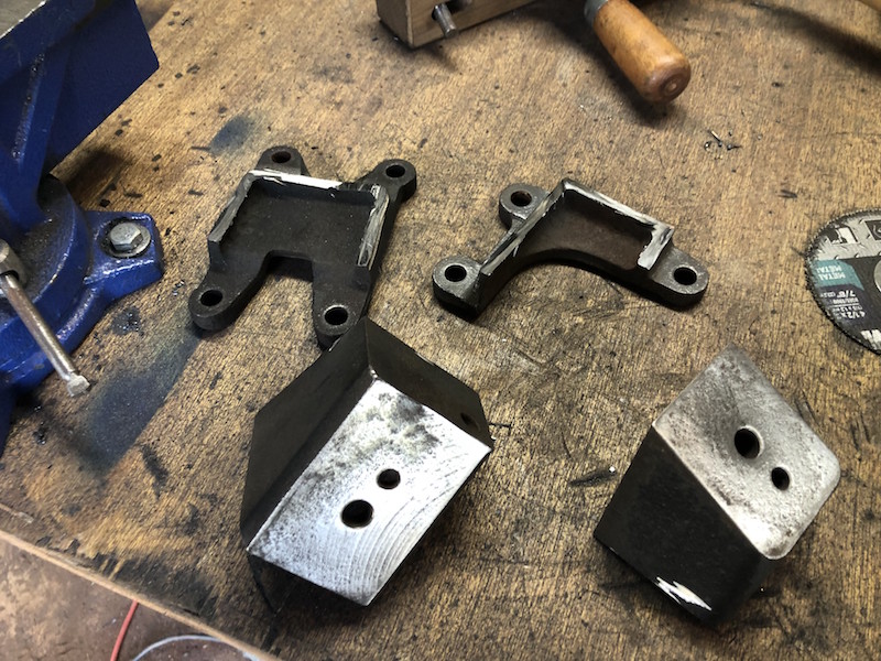
Before the car frame gets hung up for the year we will be making motor mounts for the Suzuki engine.
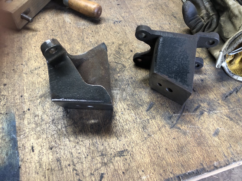
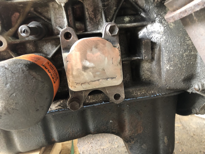
These are the cast steel motor mounts that came out of the Suzuki Samurai. While they won’t fit the new frame parts of them may be useful. I use the 4 hole casting as one mounting plate and will make a simple plate for the other.
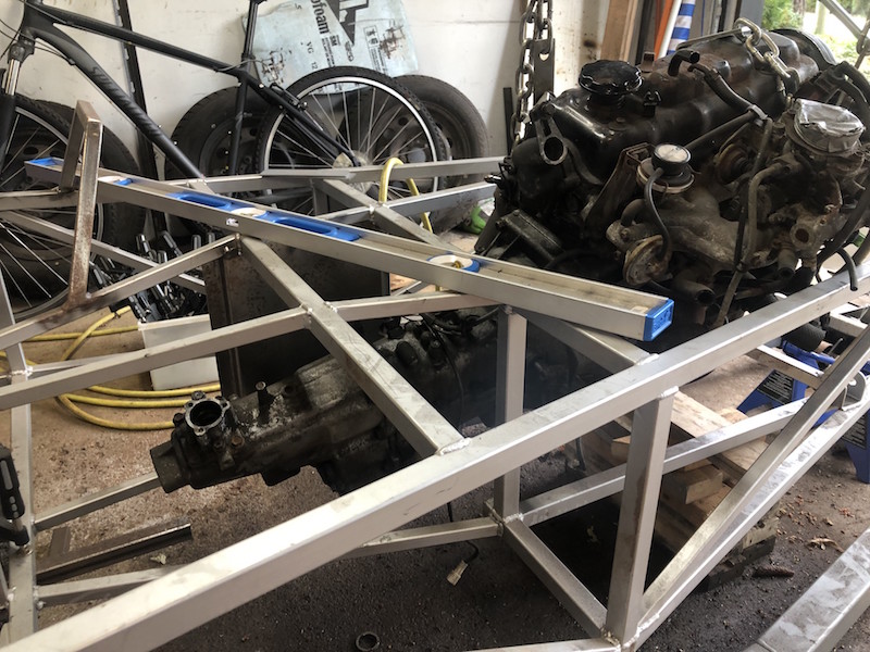
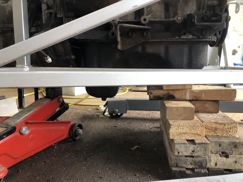
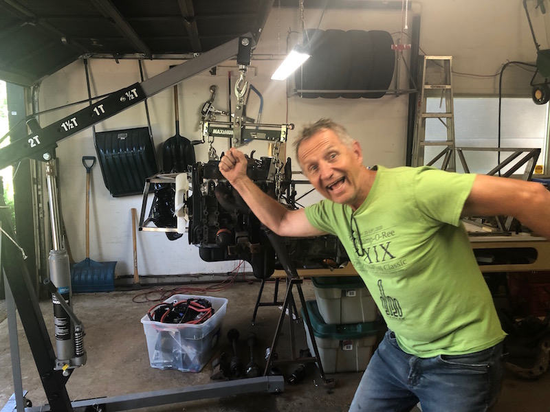
Used the engine hoist to put the motor in the frame, then leveled it and blocked it in position.
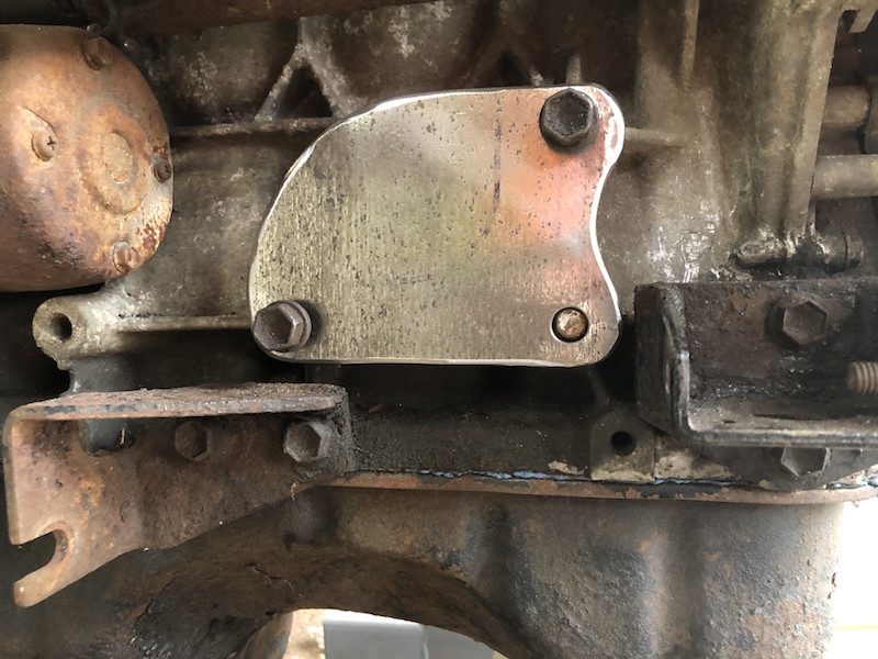
I made the mounting plate for one side of the motor and added a filler piece to the cast mount I was reusing.
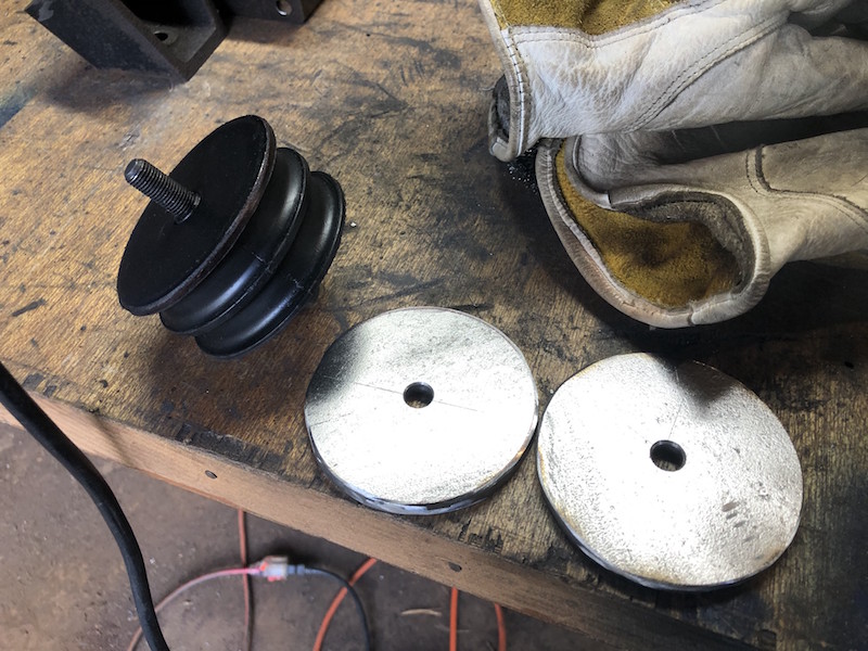
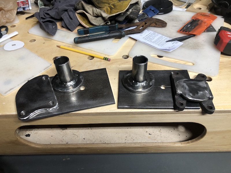
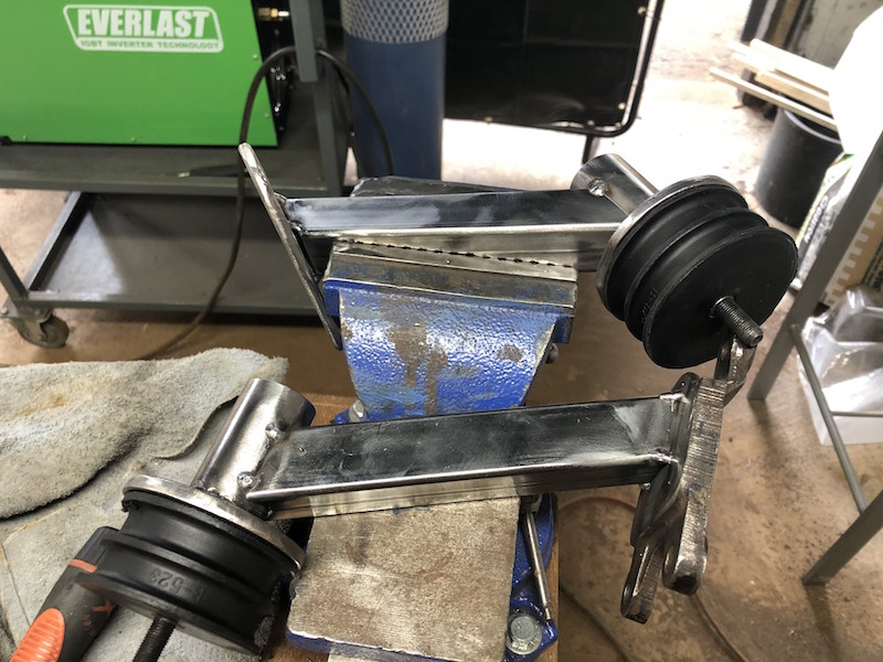
I ordered rubber motor mounts from an old Land Rover model because they were simple. I made round top plates for them and welded on upright tubes. I cut some flat plate and drilled it to act as the base for the motor mounts on the car frame.
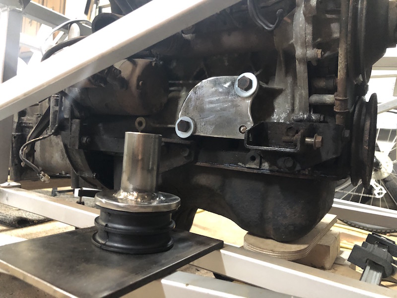
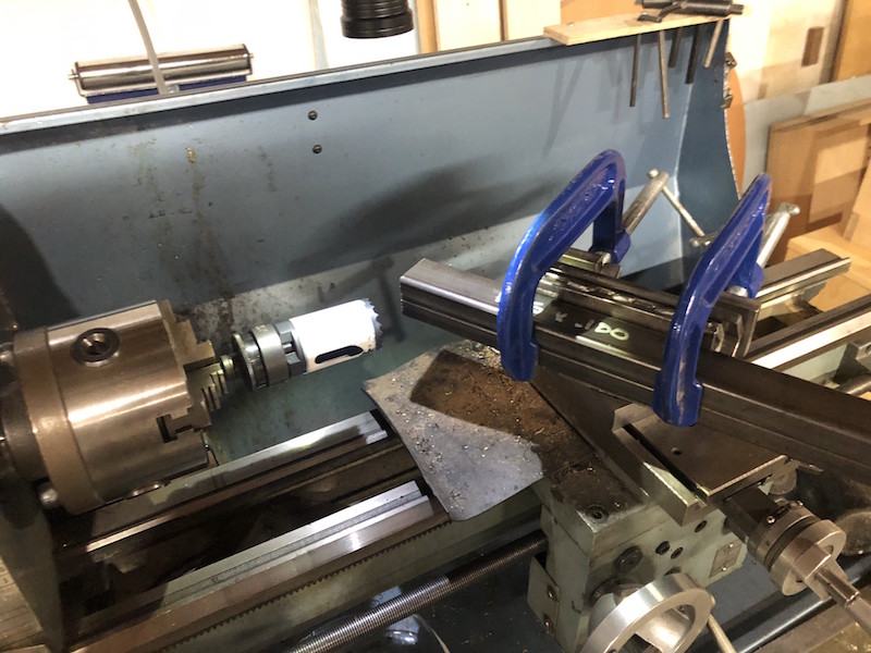
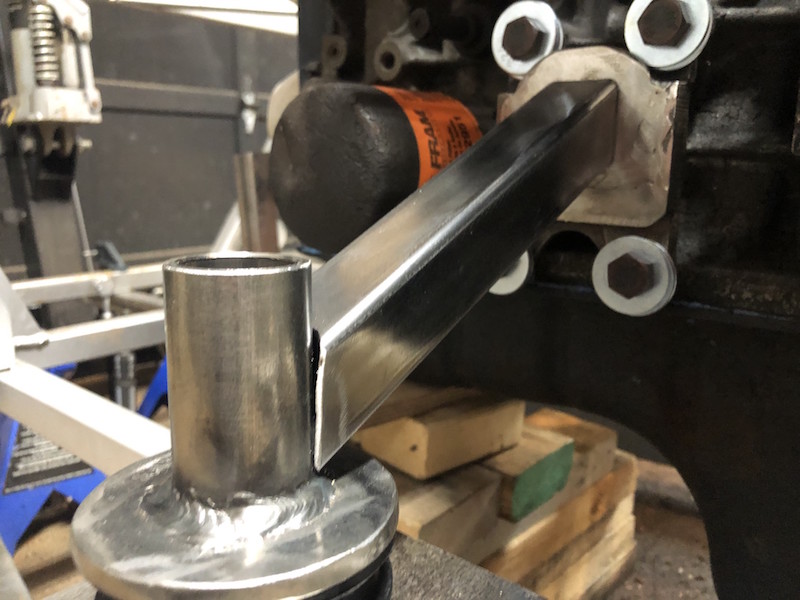
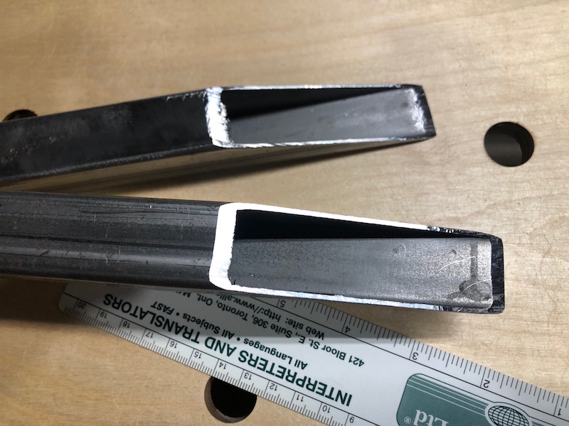
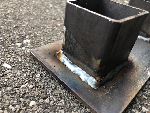
Here is the basic set up on one side. The base plate will be trimmed to match the frame members that it covers and a piece of square tubing needs to span between the mount tube and the mounting plate on the engine. The square tube will need to be notched at one end (to fit the profile of the round tube) and cut at an angle on the other to mate up with the mounting plate.
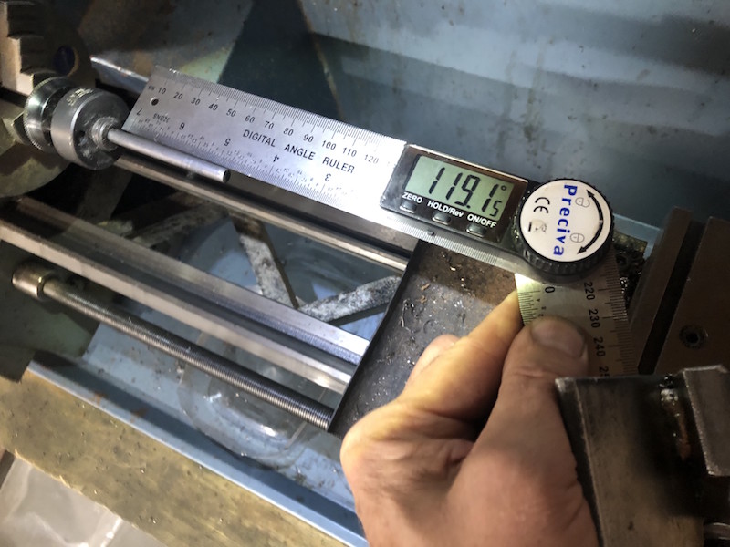
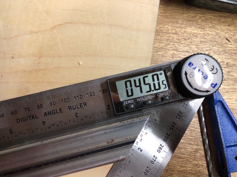
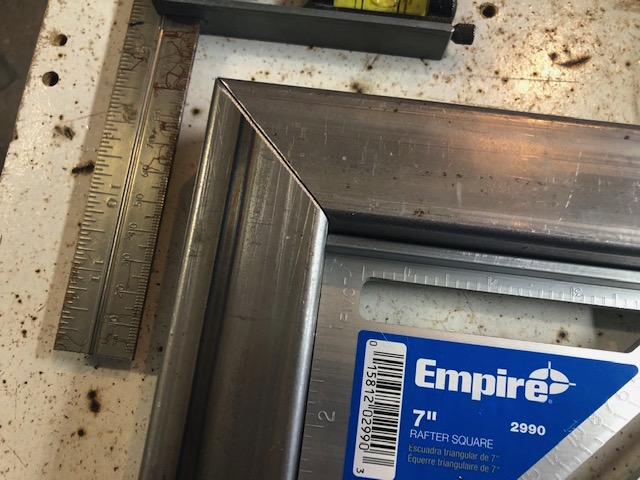
The first attempt at tube notching for production! The angle between the drill bit and tube holder is set with a Digital Angle Ruler. Then the hole saw is mounted, the tubing is clamped in position and the cutting commences. Hole saws are very coarse and so great caution and patience is needed to make a good cut.
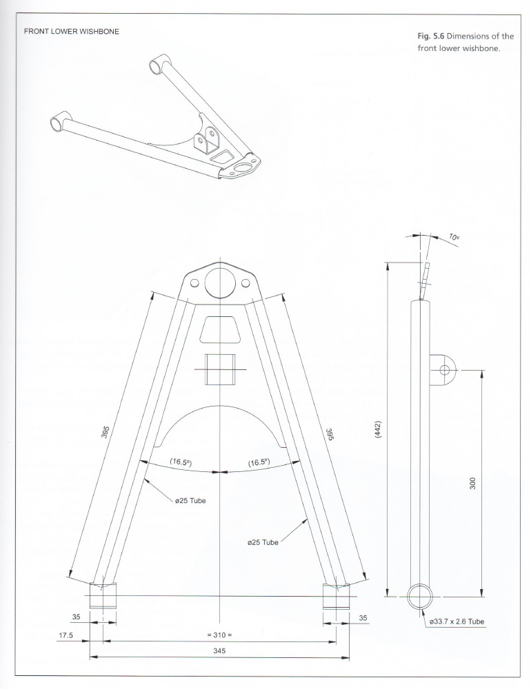
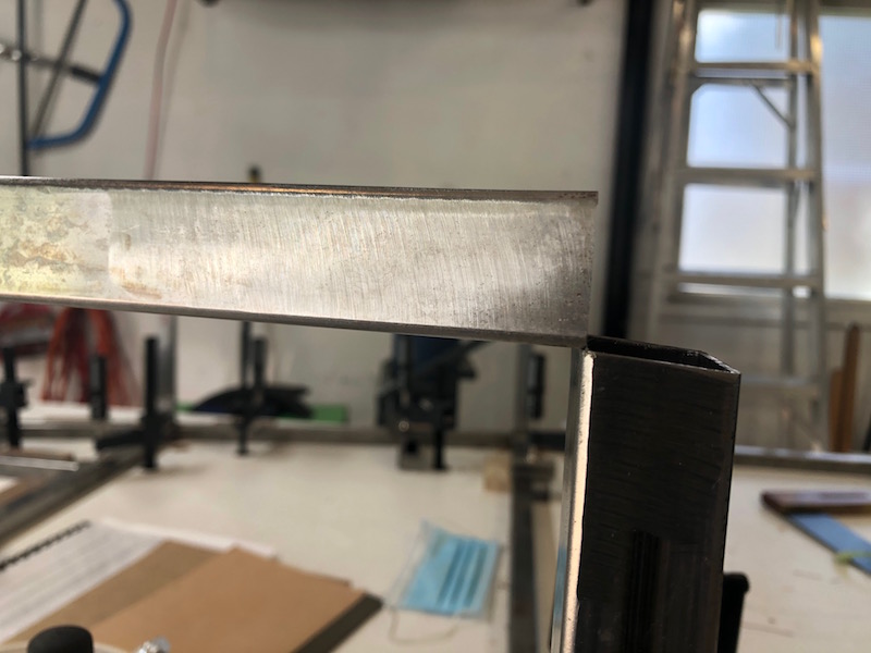
Soon it will be time to start work on the suspension components. The control arms for the car (front, back, upper and lower) are all fabricated using DOM (Drawn Over Mandrill) round tubing.
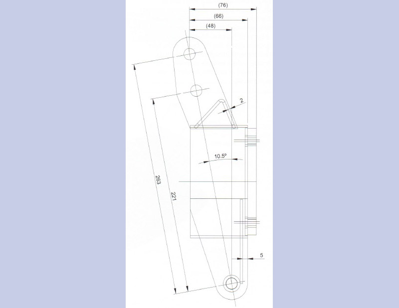
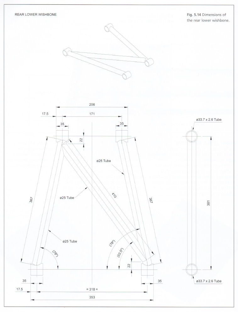
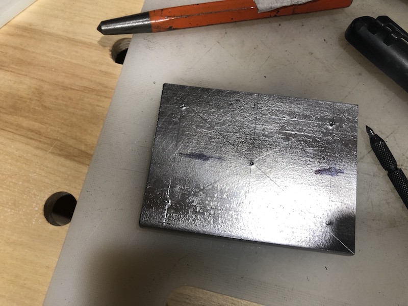
Here is the lower rear control arm geometry. It’s made up of 3 – 1″ diameter tubes that connect as well as 4 short bushing tubes. The bushing tubes provide attachment points to the frame of the car and the rear hub. How are we gonna make these?
We can’t weld a square cut tube onto a round tube, the gaps are too large and we wouldn’t get a strong joint. The solution is to notch the tubes so that the profile matches the shape of the tube being connected to. I saw “a guy on YouTube” using his lathe to do this so that’s the route I’m taking. A hole saw is driven by the lathe chuck and a sturdy fixture is attached to the lathe’s cross slide to position and hold the tube for cutting. First I need to make the tube holder.
I started with 1/2″ plate to make a base that will attach to the cross slide of the lathe using t-nuts, just like the tool holder does.
Next, I used the 4 jaw chuck, centered the rectangular base plate and drilled a center hole. I then threaded the hole while it is still on the lathe. Tapping is done by hand, manually rotating the work piece into the tap slowly just as you would with a tap handle but the lathe maintains perfect alignment and makes it easier.
Time to make the upper holder plate. Once again 1/2″ plate is used, the end is beveled to 45 degrees and extended with a triangular piece of plate on each side. A length of heavy angle iron is attached to the triangles and base. The angle iron is horizontal with the center line of the angle at the same height as the center line of the lathe chuck. A 1/2″ stud is attached to the bottom plate and passes through the upper holder allowing it to rotate and be locked down at any angle.
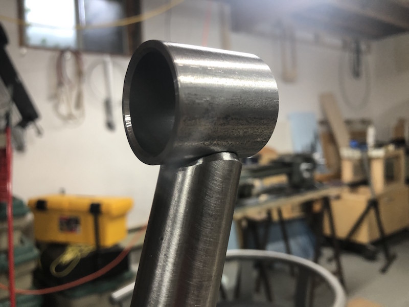
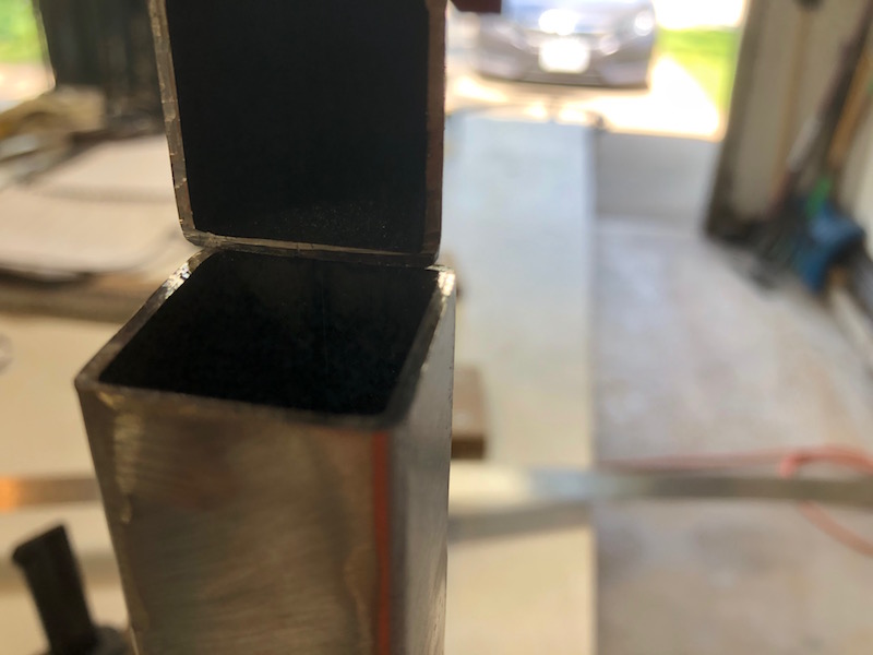
With the basic parts finished it’s time to test. The holder is mounted on the cross slide and the desired angle is set and locked. A hole saw of appropriate diameter is mounted in the lathe chuck and a piece of tubing is clamped in the holder. I use the lathe travel to manually feed the tubing into the hole saw and make the cut.
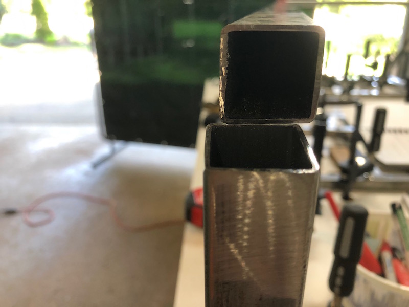
The end result is a very tight fit between the tubes.
Here are the completed components, clamping tabs were added to the top plate, a front clamping bar was made to make attaching round tube more secure and enough relief was created to allow a ratchet to be used for angle locking. This geometry means that any diameter of tube clamped in the holder will be centered on the hole saw without any adjustment needed.
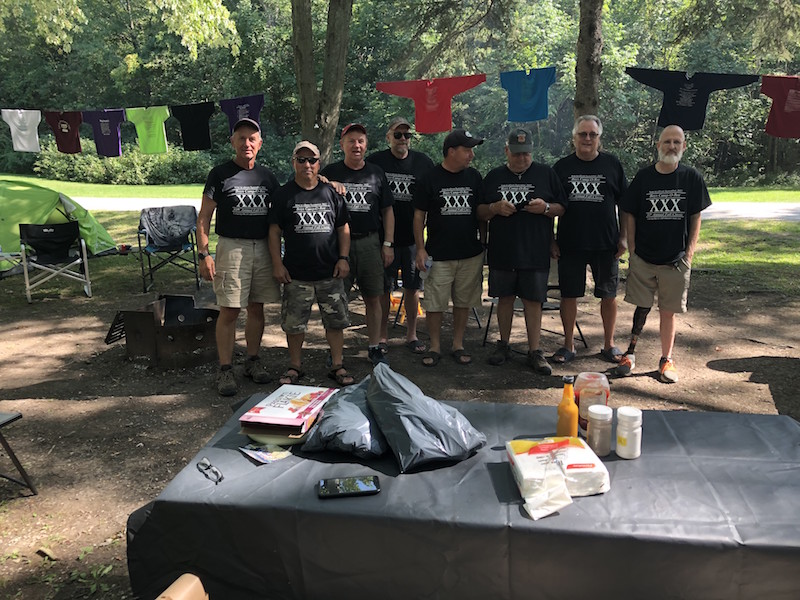
The end of summer is marked by the annual Boyz Camp-O-Ree. 2022 was a milestone event – celebrating 30 years of “camping like it’s 1991”! Tom came in from New Brunswick and the plan was for Paul and I to drive back with him, check out their new homestead and do some machining on his lathe.
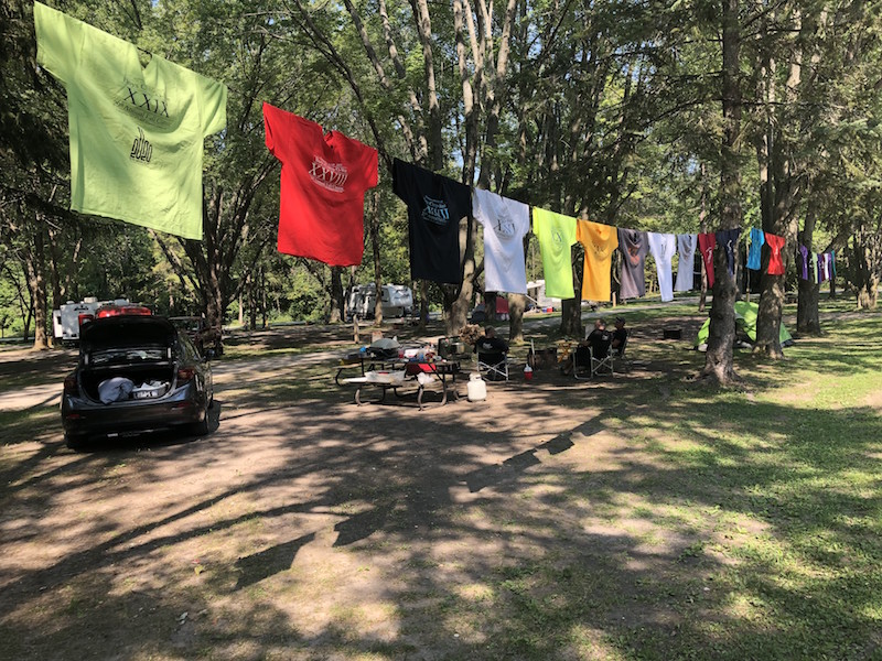
All the usual suspects were at Camp-O-Ree and the event included a static t-shirt display entitled “Camping through the years”. A good time was had by all. Before hitting the road I needed to do some pre-work.
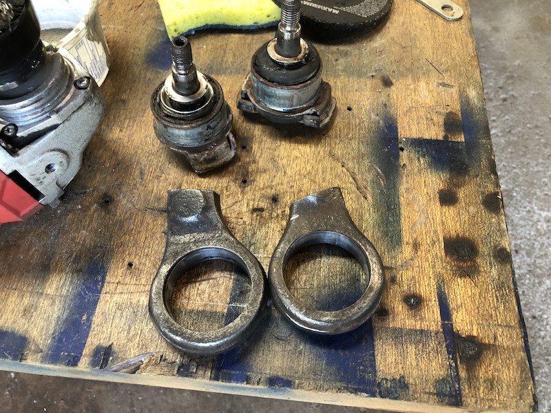
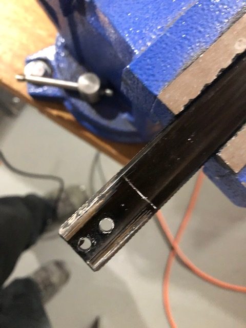
These are the ends of the BMW front control arms that were cut off before the car was sent to the scrapyard. The plan is to reuse them in the new Locost control arms. They are part of a heavy steel casting and need to be trimmed and turned on a lathe to get them ready.
Trimmed with the chop saw, cleaned up with the angle grinder and ready to visit the lathe.
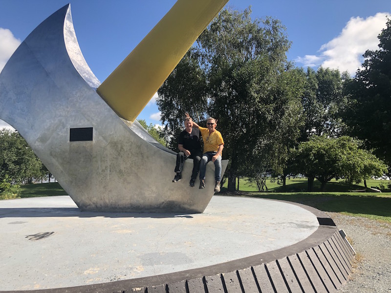
We made it to Nackawic, saw “the” sight and helped do some yard work.
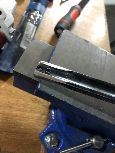
Tom gave me a quick lesson on using the lathe and I was able to clean up the front ball joint holders. I hadn’t operated a lathe since grade 10 shop class and was pretty rusty. Tom insisted that I “borrow” the lathe since he figured I would have a lot of need for it in the next while. Boy was he right! With the lathe loaded in the trunk of the car Paul and I headed back to Toronto.
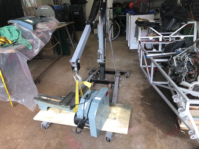
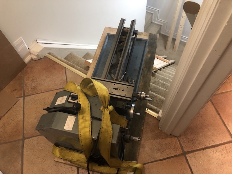
Thankfully I had the engine hoist to get it out of the trunk. Next problem how to get it into the basement?
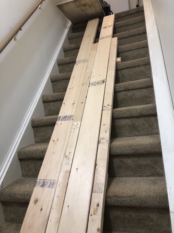
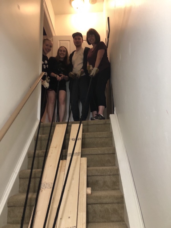
Emily didn’t think it was a good idea to just “go for it” and try to hump it down the stairs (smart girl). I made a ramp and it slid down very easily with everyone supervising.
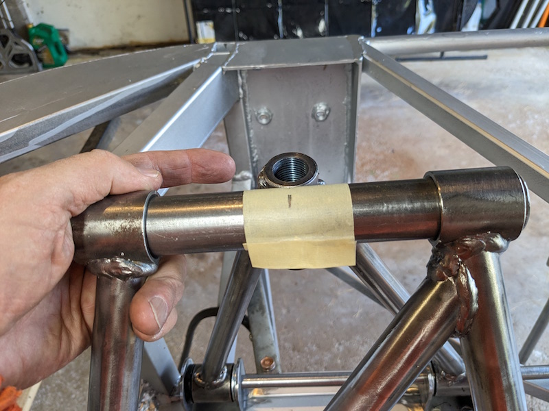
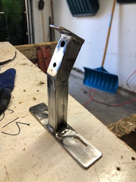
The Lo-cost front suspension uses upper and lower control arms, ball joints and a coil over shock. The BMW doner front end has a lower control arm with ball joint and and a McPherson strut for the upper connection. I need to “design” and fabricate an upper ball joint adapter to replace the strut.
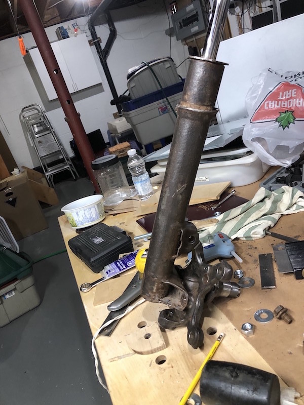
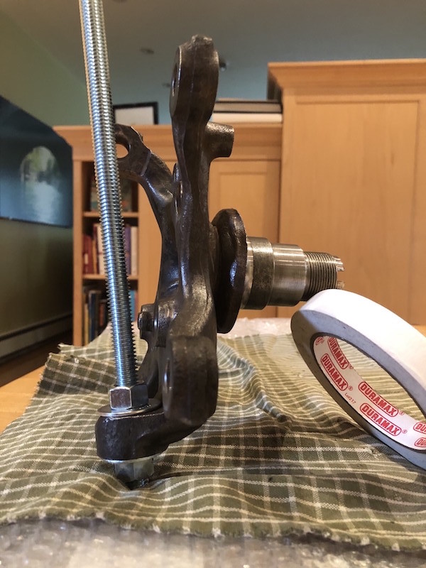
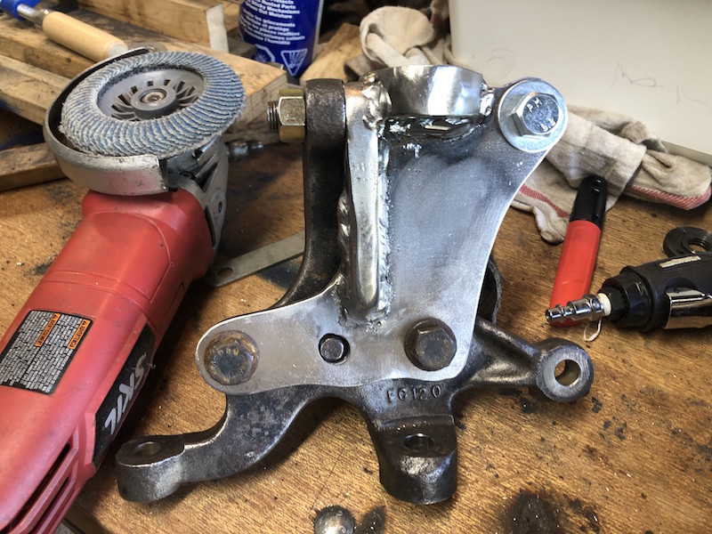
The McPherson strut as it attaches to the BMW hub.
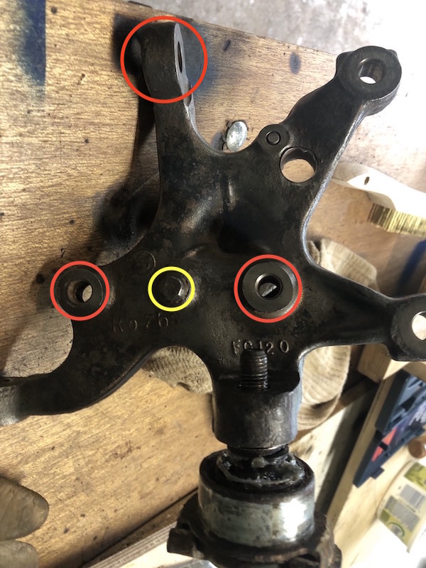
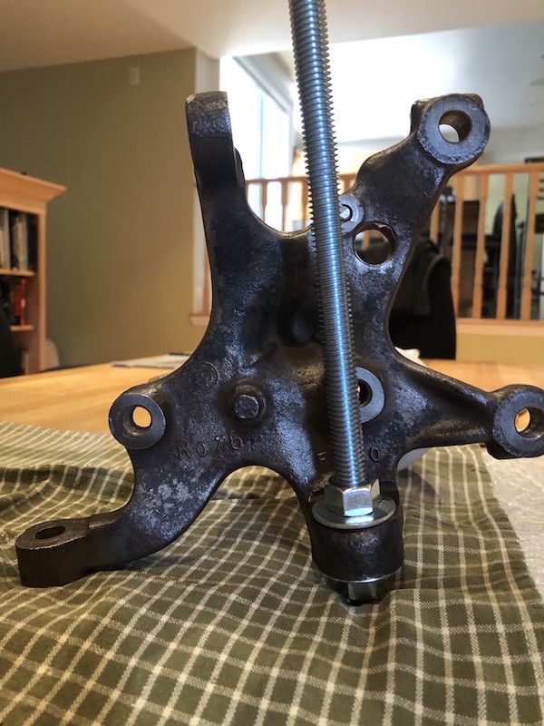
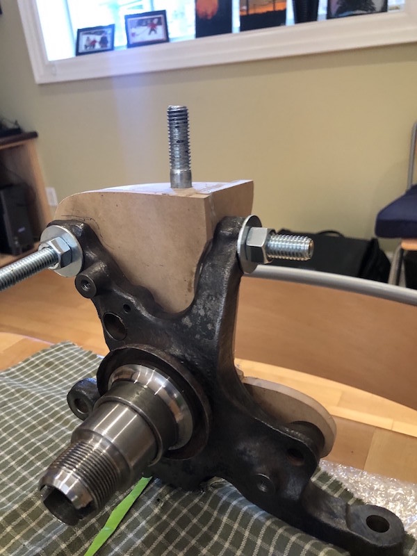
Here is the back side of the front hub with a lower ball joint in place. There are the 3 dedicated mounting points (plus a locating stud circled in yellow) for the strut. The other two mounting points are for the disk brake caliper.
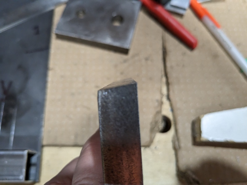
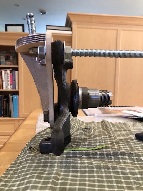
A couple views of the a hub with a threaded rod clamped through the lower ball joint boss. This rod was used as a reference for the location of the upper ball joint.
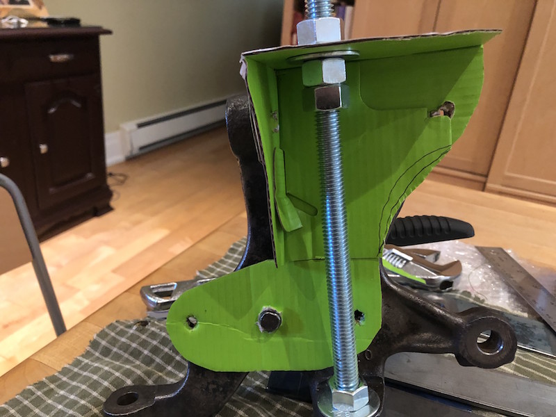
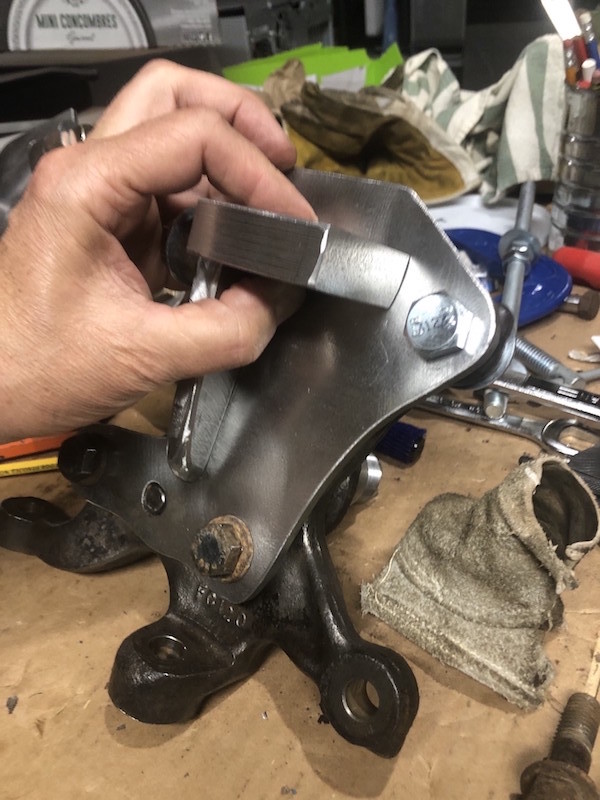
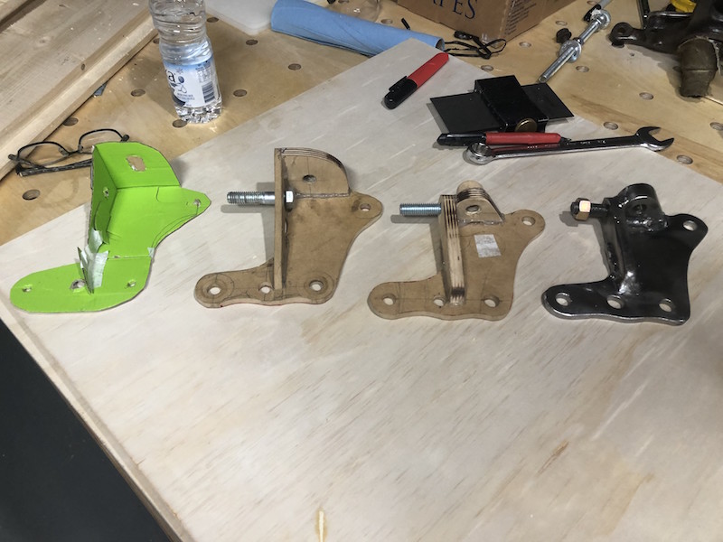
As a first step, I pieced together a cardboard mock-up of what a ball joint holder may look like.
Next, I made a wooden mock up to see how a solid model with realistic material thicknesses would work. The backing plate and web are 1/4″ thick and the top deck is 1/2″ material. This holder actually bolts on to the hub in 4 places (!) using one of the brake caliper mounting holes as well. The threaded rod and nuts/washers were used to position the top plate.
A couple of views of the wooden mock-up attached to the hub. The top deck attaches to the backing plate at an angle to keep the upper ball joint in line with the lower one. The whole structure is a bit taller than I would like and the bolt that passes through the upper strut attachment boss is awkward to get at. Time for a second iteration.
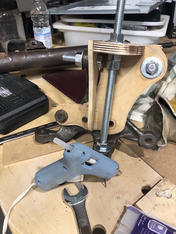
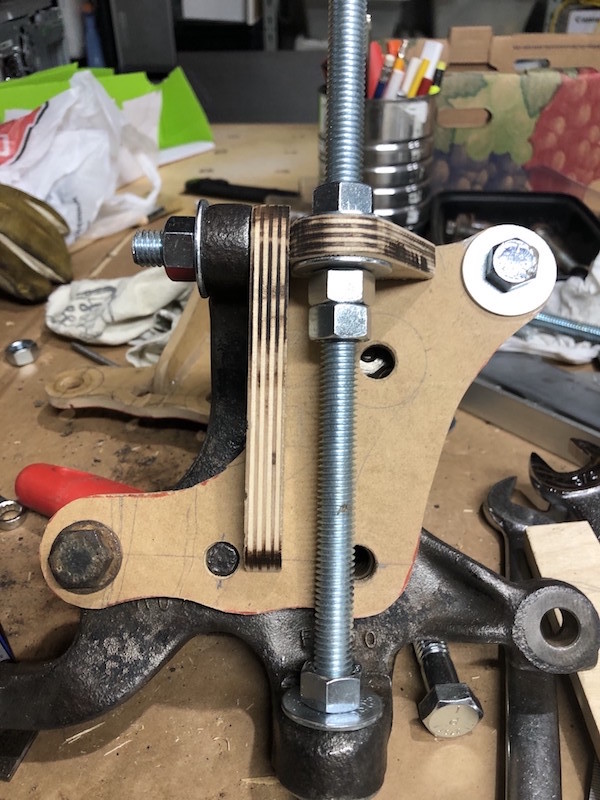
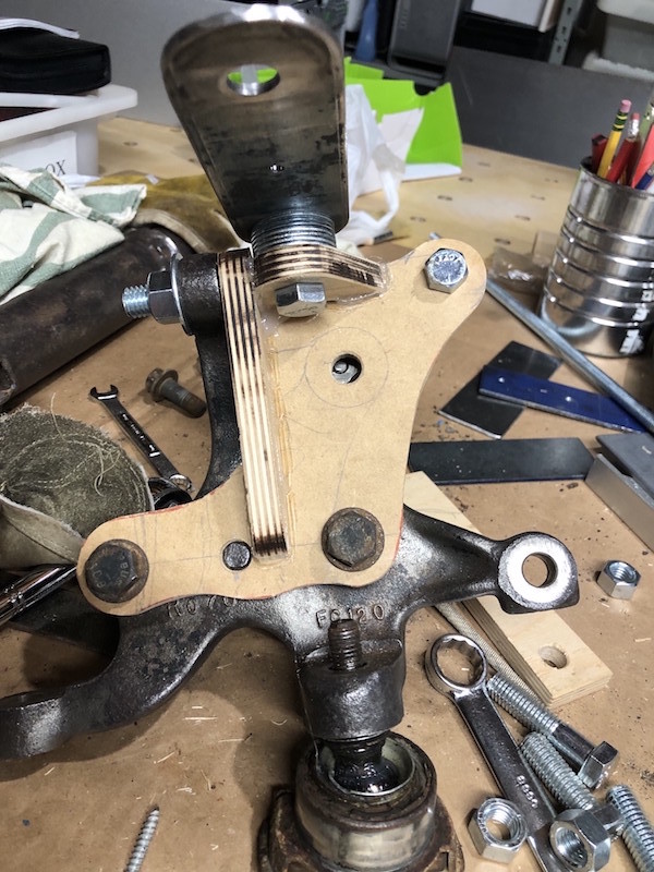
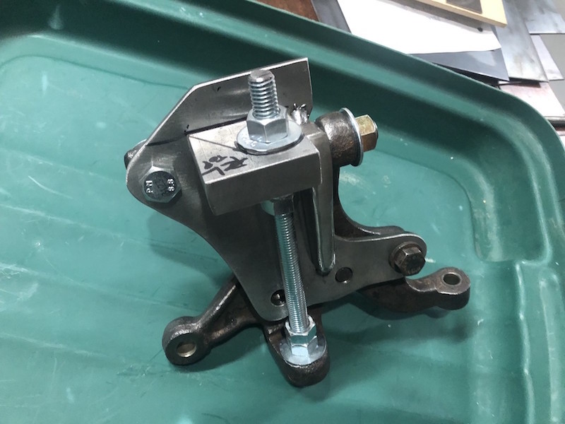
Here is the Mk II model with a lower height, a bit too low as it turns out. I need to raise it a bit to insure that the suspension arms don’t interfere with the hub during movement. On the right some washers were added to raise the control arm attachment position to check things out.
Here are the Mk I and Mk II mock ups. The Mk II is shorter and will use a stud to attach to the top boss on the hub rather than a bolt. The web is now 1/2″ thick to accommodate the stud. Wooden models are a great way to develop a complicated part. Wood is quick to cut, easy to shape, and fast to assemble using a hot glue gun.
No CNC cutting here! 1/4″ thick backing plates are drilled for the bottom 3 holes and ready for cutting with the angle grinder.
Rough cut and fitting on the hub.
Lots of consumables later….
The backing plates fitted on the front hubs. They were ground to the final shape using flapper disks and a surfacing disk got rid of the mill scale. Some trimming is still required on the top but we need the web and top plate fitted first.
1/2″ plate was cut, drilled and tapped for the web.
The webs were ground to their final shape and 1/2″ studs installed. Here the back plate is attached to the hubs and the web bolted onto the upper boss.
Creating the top plate was more of a challenge. They are going to be 3/4″ thick to provide a suitable depth for the ball joint taper. The chop saw cut the 3/4″ plate to the correct angle to meet the back plate. That saw is amazing!
The top plate hole position was carefully measured, marked and drilled. Now the threaded rod, nuts and washers can be used to set the position of the top plate. The top plate is marked to be trimmed to the final shape.
A tapered ream was used to open up the hole in order to match the taper on the ball joints.
With the top plate cut and ground to shape I could determine exactly where to trim the top of the backing plate.
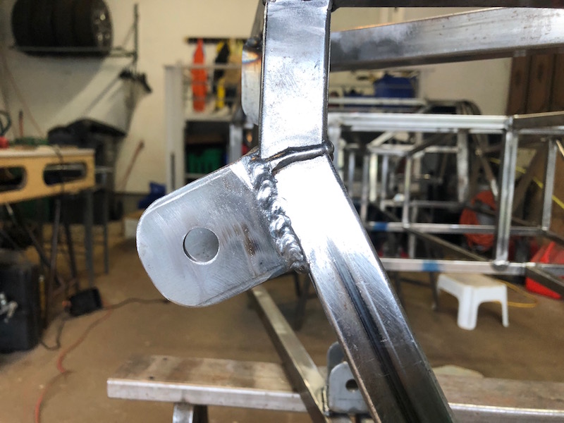
A few practice welds on some heavy plate and the ball joint adapters get fully welded.
The finished product is pretty compact and looks massively strong. In the Lo-cost design the upper control arm is not constrained, the coil over shock attaches to the lower control arm. This means that the lower ball joints carry the weight of the car and the upper ball joints see much less load.
The progression from origami to finished component!
Okay, I did promise to keep on top of the blog when I last posted two years ago (December 2021 yikes!). In my defense, it has been a busy time and car progress has been a bit “spotty” so I never really got into the blog. Sorry about that.. but let’s get on with the story.
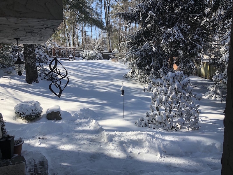
The winter of 21/22 came, stayed a while, and went…
and when it did I got to retire – complete with Lo-Cost 7 car cake and custom “G.T.F.O.” license plate!
The car eventually came off the ceiling and work could commence.
Cutting sheet metal for the firewalls.
Tacked in place
Added the driver’s side steering and dash frame.
Time to dismantle and clean up the front hubs.
Fortunately, most of the rusty sheet metal bits are not needed.
Here are the important bits in need of cleanup.
Angle grinders with wire brushes and a pneumatic needle gun do the job.
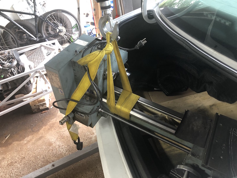
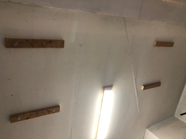
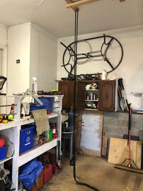
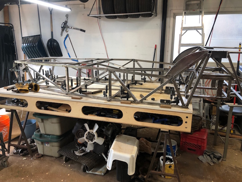
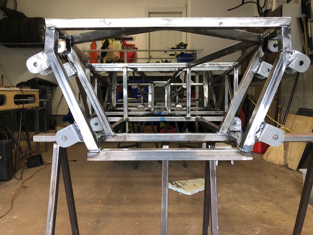
The arrival of winter is immanent and it is time to get the frame out of the way so the cars can occupy the garage. We will be hanging it from the ceiling for the winter.
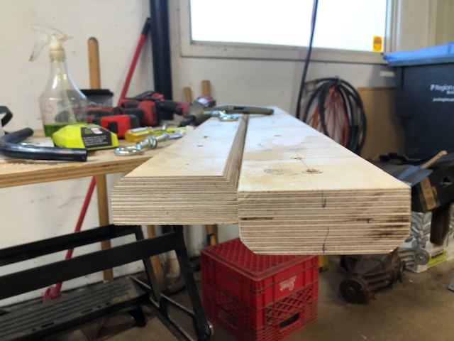
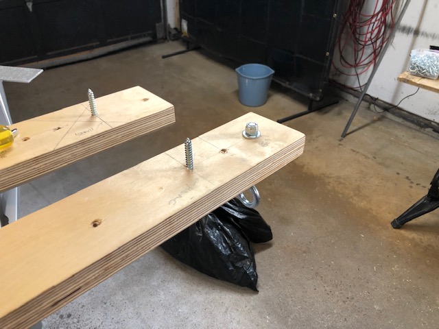
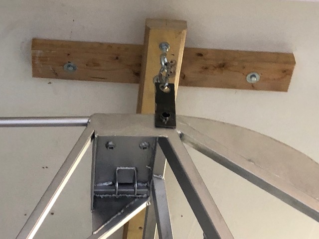
I lag bolted four cleats into the ceiling and cut cross beams from some laminated plywood 2×4’s that I glued up for some reason and never used. These would be lag bolted across the ceiling cleats and the frame hung from eye bolts.
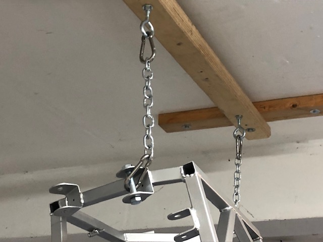
It was also a last chance to do some fabrication. I wanted to make brackets to attach the back of the frame to the eye bolts. The round tube slides into the open tube that the roll bar plates attach to and the frame hangs from the open hole.
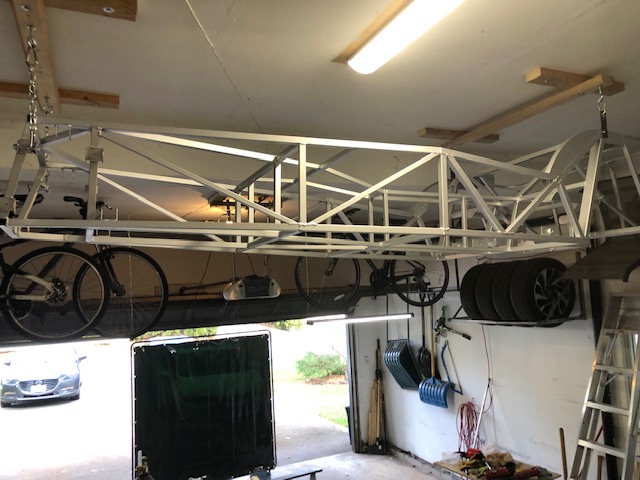
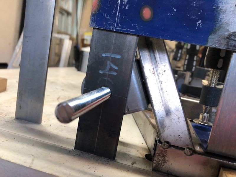
The frame has gone up a few weight classes, it now tips the scales at 140 lbs.. Before hanging it up I checked to make sure that the whole arrangement wouldn’t come tumbling down by swinging from each of the eye bolts on a sturdy rope. Then I used the rope over the cross beam to hold the front of the frame and stood it on end. The front was attached from the suspension brackets using a short length of chain and some spring loaded clips (rated for 350 lbs.).
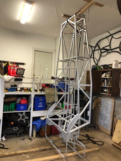
The back end was more work. With Erik assisting and the rope over the cross beam we swung the frame up as high as we could. We then pushed it higher, propping it up with a couple 2×4’s. A final push with one of the 2x4s lifted it to the ceiling. At that point it was held by the rope and I was able to scurry up the ladder and attach the clips. Sorry no work in progress pictures our hands were full!
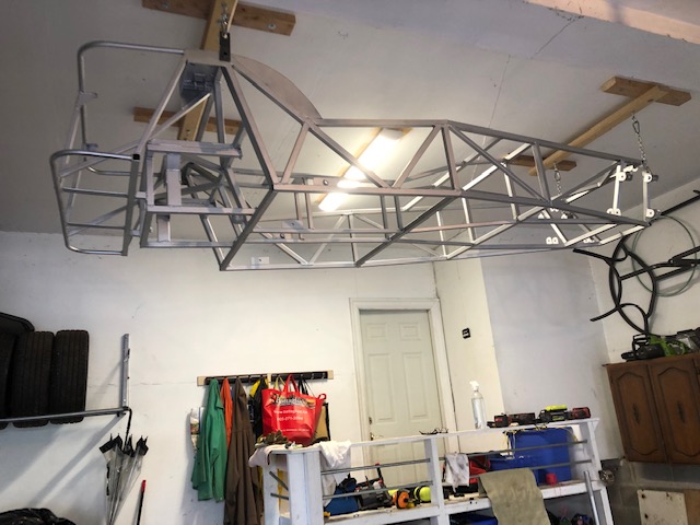
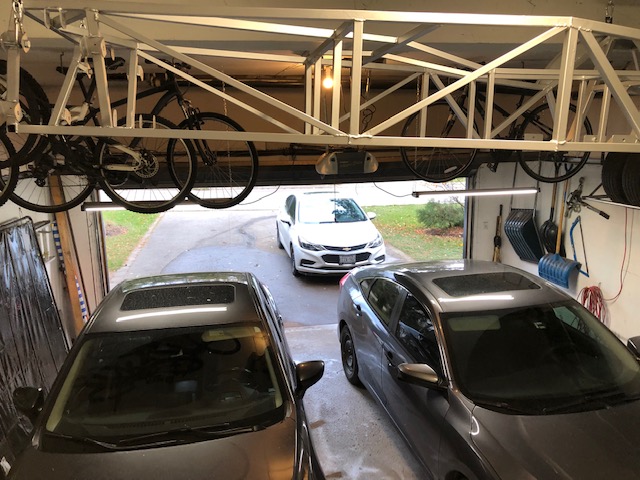
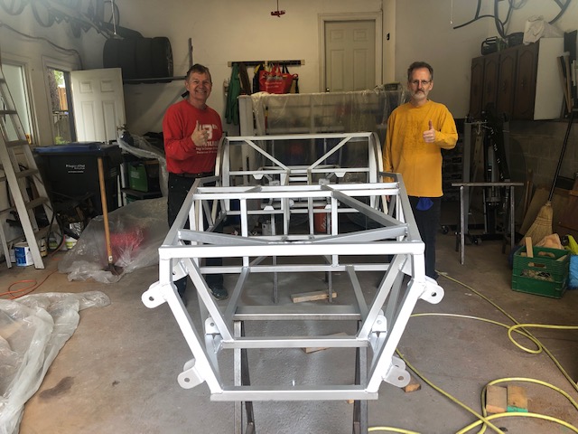
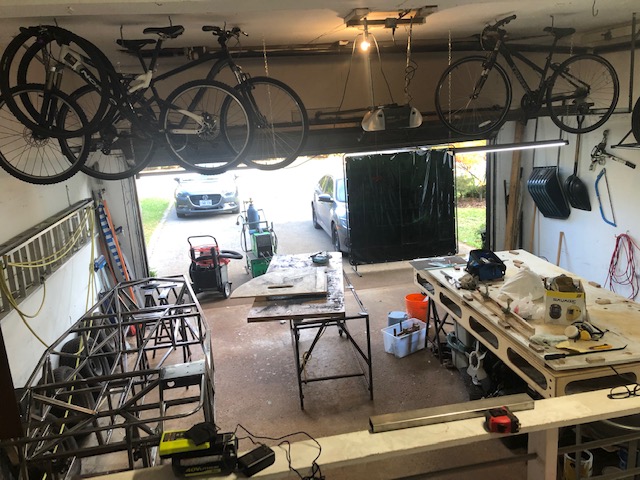
The garage has a high ceiling so there is still 8 feet of headroom under the frame, even Erik won’t hit his head. With the new paint job the frame looks great hanging there, even Joanne likes it!
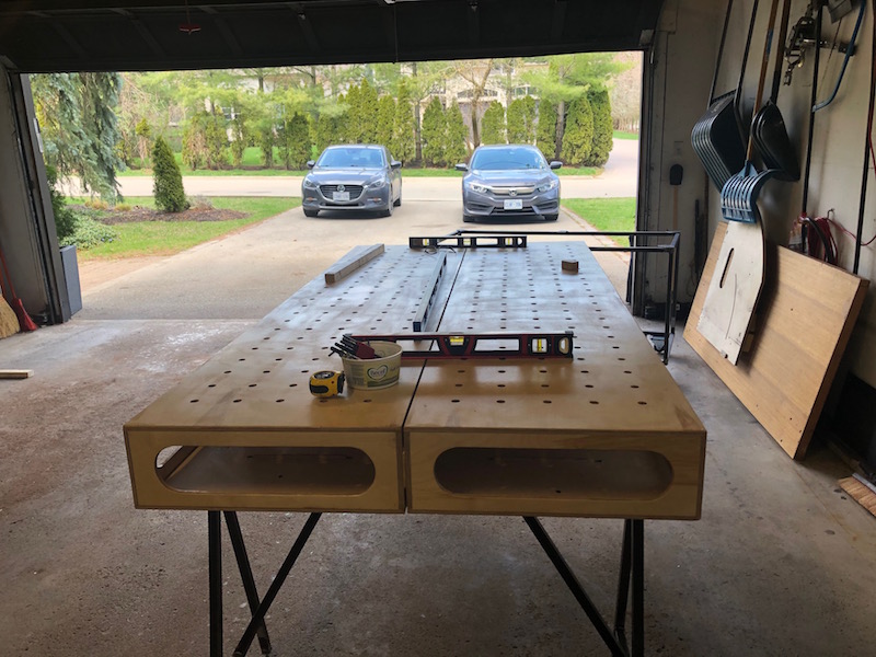
Both cars in the garage for the first time since April and none too soon!
It has been a fun getting the blog up and running. Over a years worth of pictures and build to get through! I have learned my lesson and will be blogging regularly as progress is made on the car.
I have work to do in the basement getting the shop set up and lots of family/house stuff to get done for Christmas. Look for the next post early in the new year!
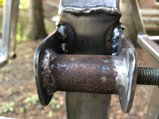
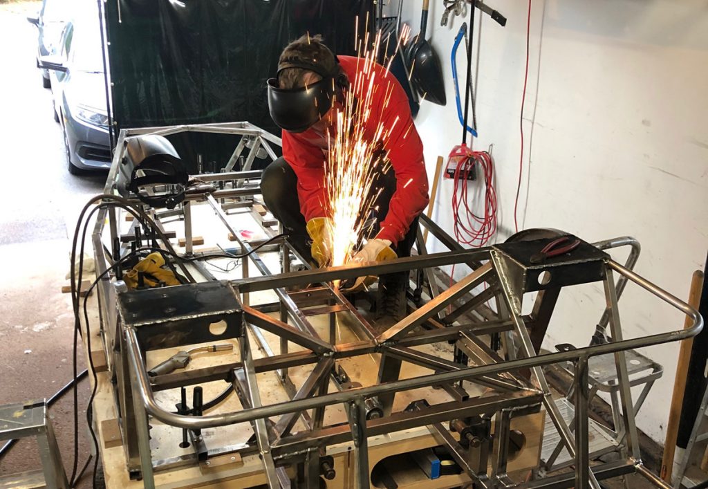
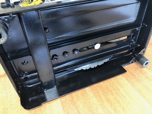
The last thing to do for the season is to get a coat of paint on the frame so it won’t rust. Before that can happen it needs to get cleaned up. So the frame gets muscled around the garage and the angle grinder/wire brush wheel combo gets a work out. Along the way I found the odd weld that was missed and fix them. I also added a gusset to support the front upper suspension brackets where they overhang the back of the frame tube. Thanks for that bit of advise Herman.
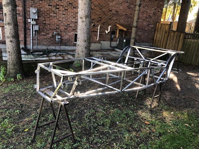
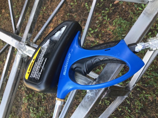
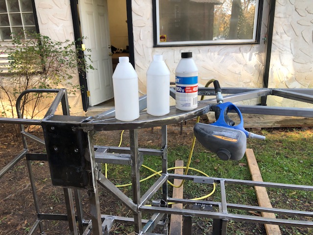
I put the frame in the side yard so that I could try a small spot blaster to clean up some hard to reach spots.
I went through three bottles of abrasive pretty quickly but it seemed to work pretty well. Before and after shots.
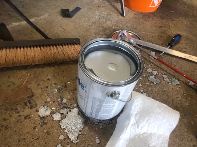
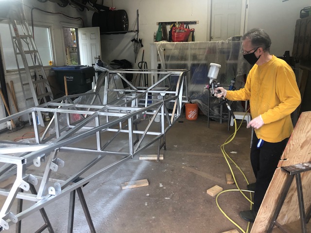
Paul headed down from Barrie with his HVLP spray gun to paint the frame. I bought a gallon of weldable primer that should prevent rusting and can be welded through where required next season. The primer seemed pretty thin even when all the thick goo in the bottom was stirred up. Paul put on two coats and the gun worked very well. There was very little over spray and we only used about 1/3 of the gallon of paint, enough left for two more cars!
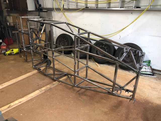
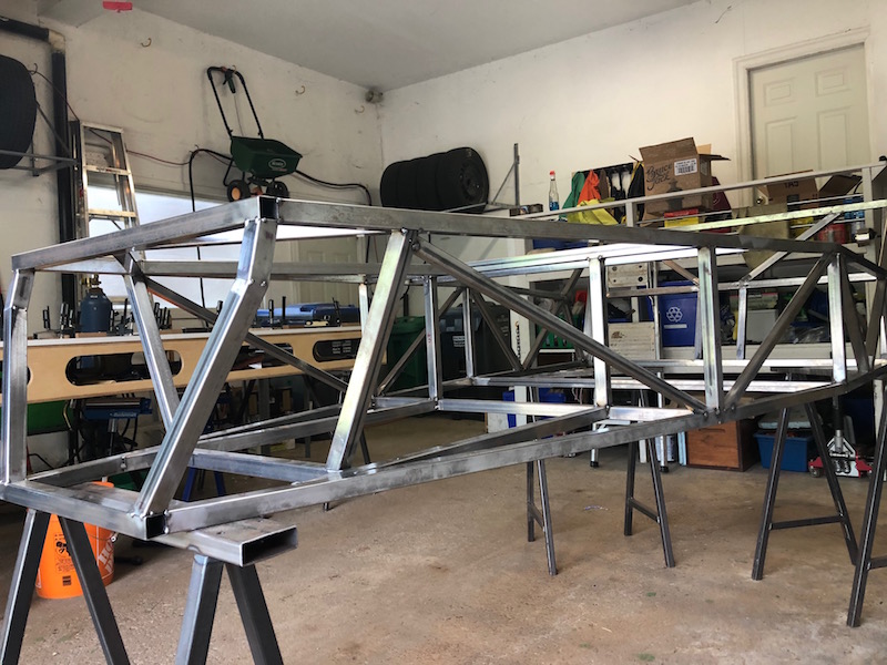
It looks terrific, Paul did a great job! A coat of paint makes everything look better, even my welds! We stood around admiring it until we started shivering – it was pretty chilly.
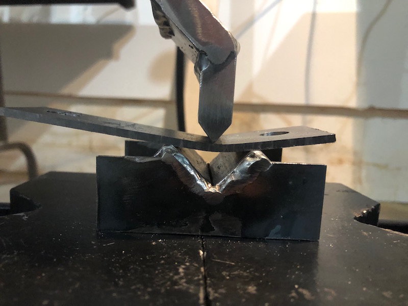
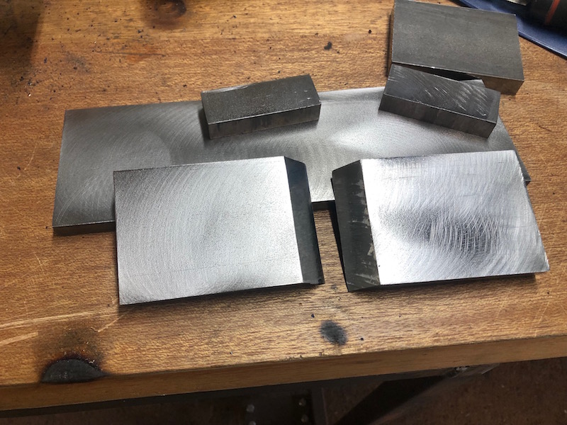
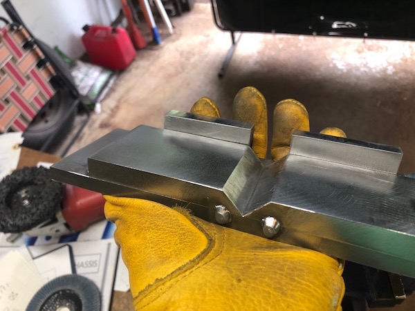
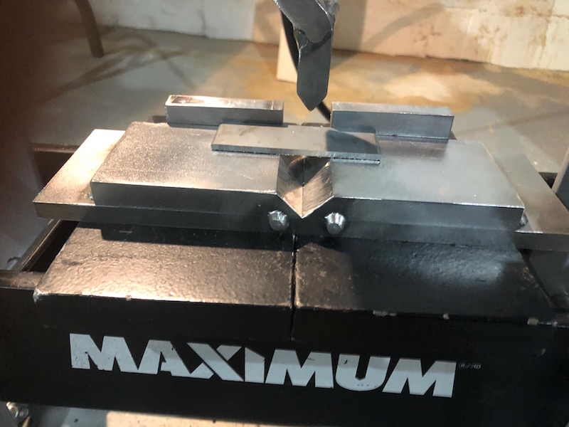
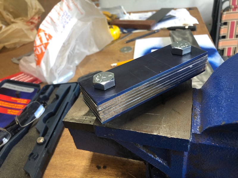
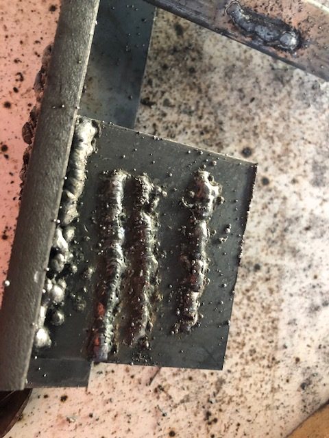
Time to fully weld the frame. I have to admit that next to getting the the front suspension brackets aligned, this is a task that I was most worried about. It is very difficult to be consistent when you are an inexperienced welder. Also, having to weld in and around other parts of the frame and in awkward spots will be challenging. Since I have been mostly tacking stuff together for the last several months I thought I should do some welding before getting into the frame. So I grabbed some scrap bits and started.
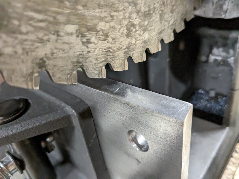
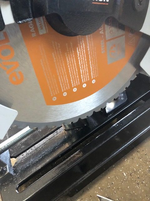
I welded up some pieces that looked pretty good and cut through the welds on the chop saw to have a look. Things seemed good but without etching, polishing, using a microscope and knowing what you are looking for could you really tell?
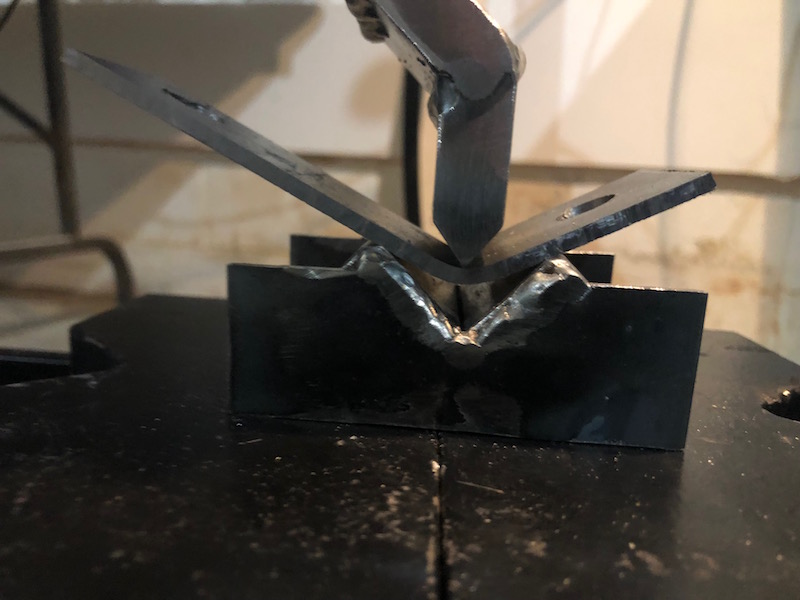
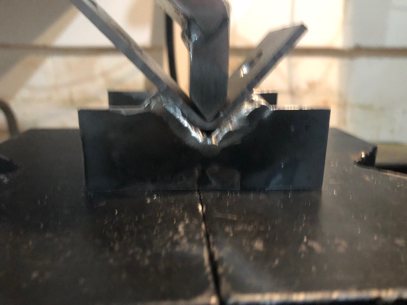
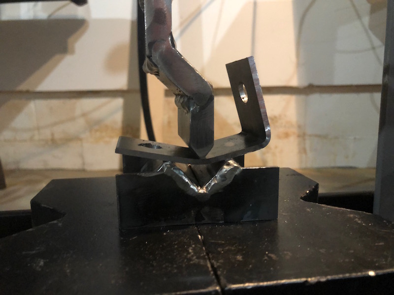
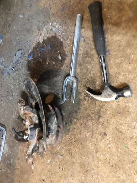
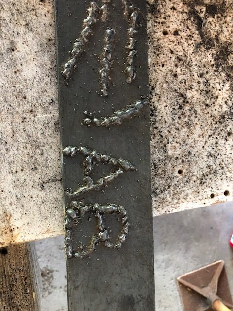
I developed a more practical approach, I welded more samples, clamped them in the vise and hammered them with a 5 lb lump hammer to find out what was going to give. The results were pretty encouraging so on to the frame.
I had done some reading about welding sequence where they recommend welding the joints that will cause the least distortion first. So welding a butt joint before welding a fillet in a 90 degree joint makes sense. I set about welding all of the butt type joints on the bottom frame tubes since it was clamped solidly to the bench. I worked around the frame doing opposite sides and moving front to back randomly. I then moved up to the steel above the table in the same manner. I used the grinder to take down the tacks before welding as they would leave a lump if I tried to weld through them. After all the butt welds were done I moved on to the fillet welds. Again left, right, front, back, bottom to top. I left the suspension brackets till last since they are fairly important, holding on the wheels and all. I wanted as much practice as possible before tackling them. That strategy seemed to pay off!
At some point the frame needs to come off the table so that the bottom can be welded. At this time I also used a Forstner bit to relieve the MDF bench top at all the joints. That way I could put the frame back on the table and the weld wouldn’t keep it from lying flat, the beads would sit in the recesses. That worked out, the frame is still flat.
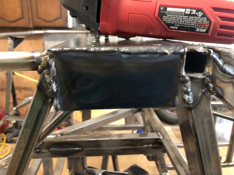
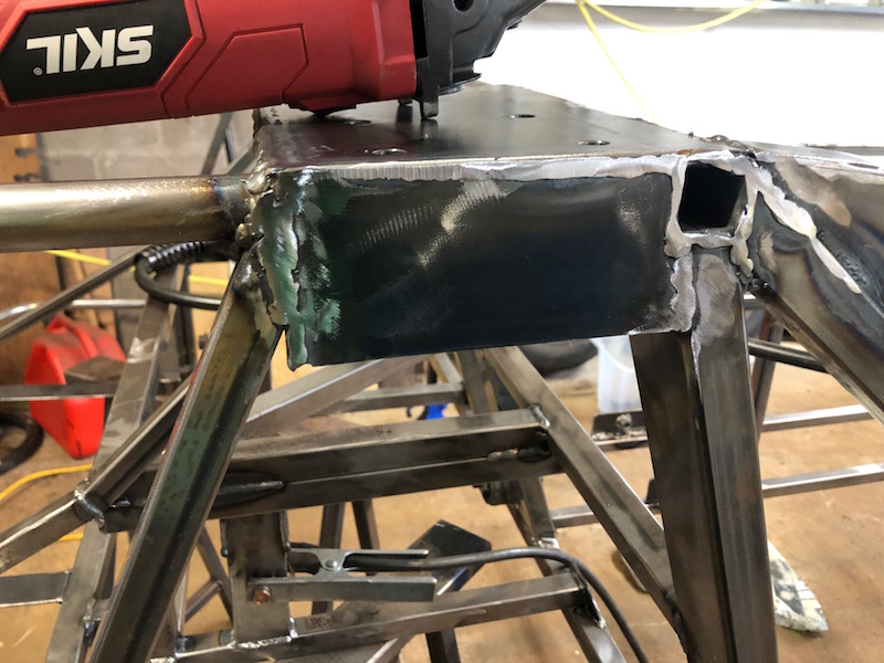
I had to clean up the boxed in roll bar mounts. I made a lumpy mess of the outside seams. Fortunately I had also fully welded the inside of the boxes when the frame was on it’s back. Angle grinder to the rescue – again.
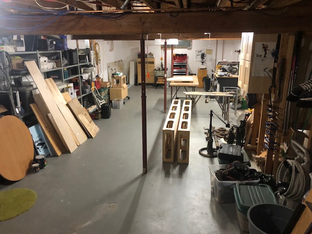
With the frame fully welded it was time to move the shop back to the basement. It’s mid November and winter is coming. Dismantling the benches and shifting everything downstairs.
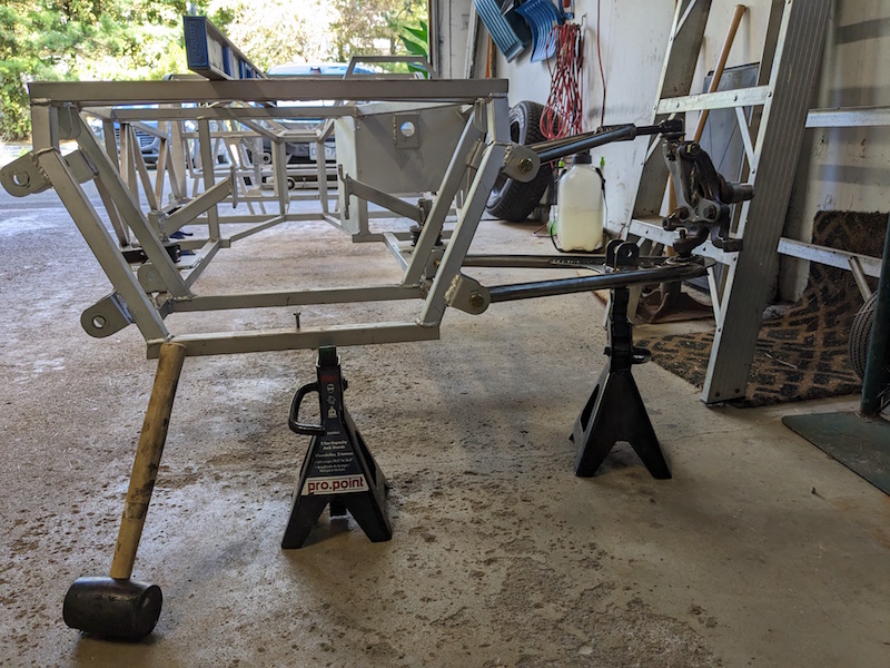
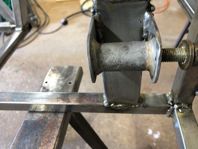
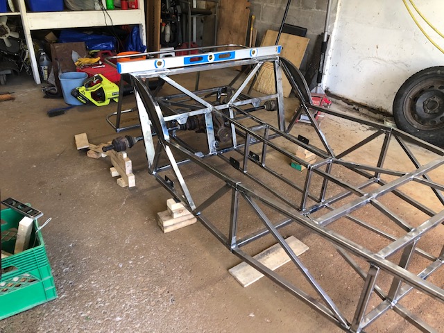
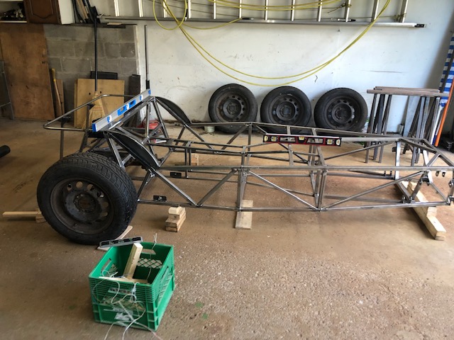
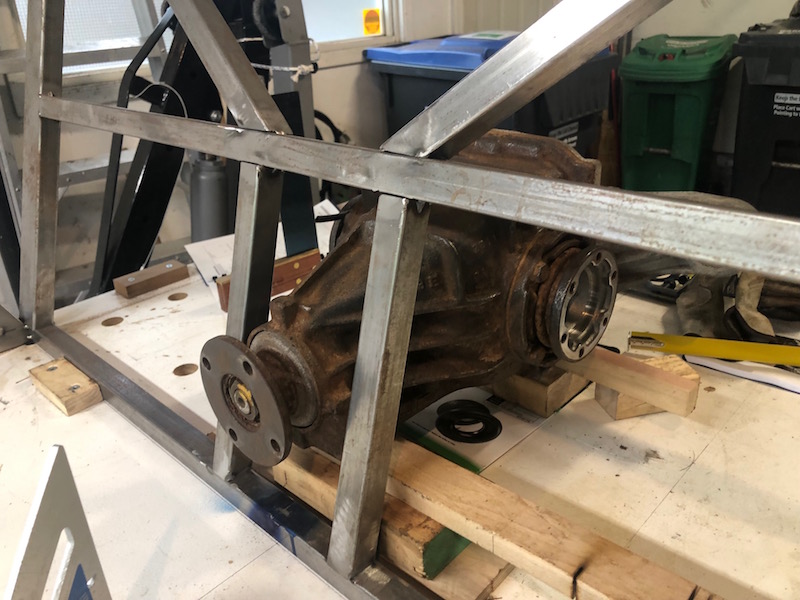
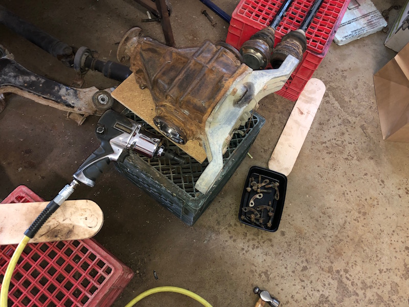
With the garage empty I thought I would see how the ride height of the car was looking. I blocked up the frame and leveled it. Then I bolted the differential in place and put the half shafts back on.
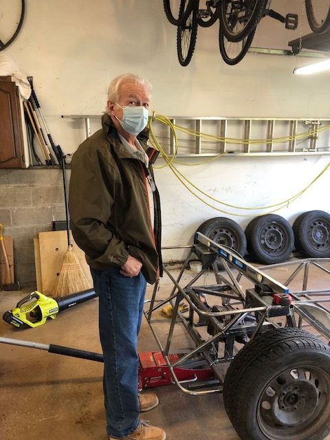
My chassis consultant, Herman stopped by. He’s a neighbor with a lot of experience driving, building and racing high performance sports cars (Porsche mainly). He also owned a Lotus 7 back in the day. Herman is a wealth of knowledge and good ideas about how to improve things on the Locost.
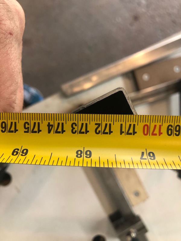
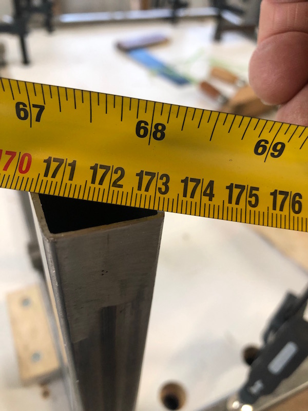
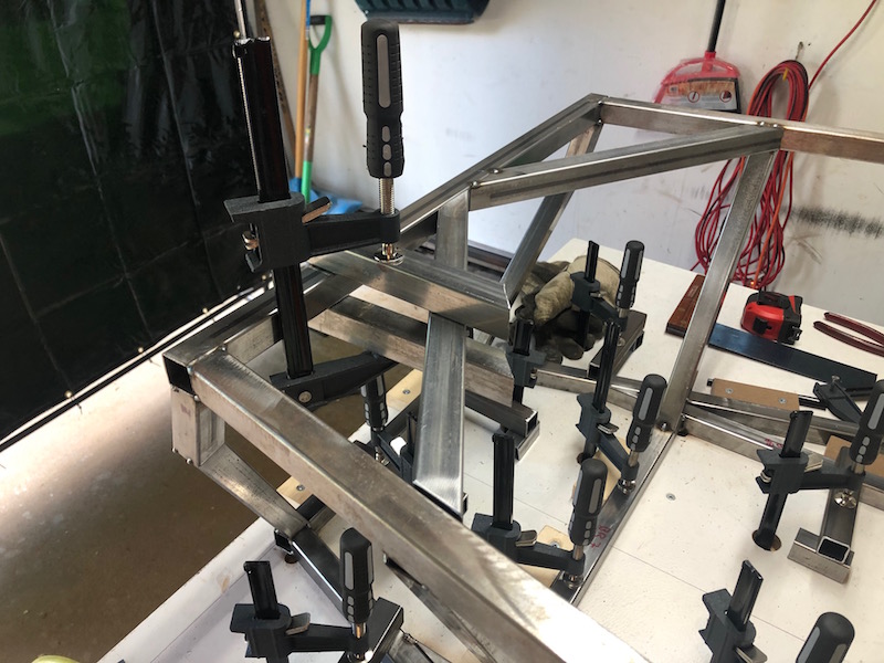
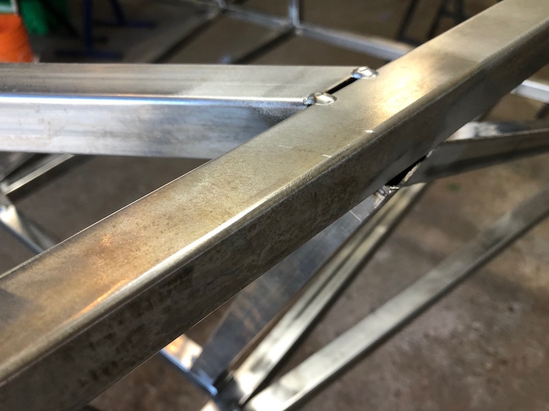
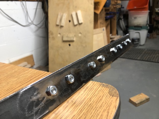
Time to attach the suspension brackets to the infamous front frame…
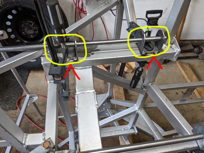
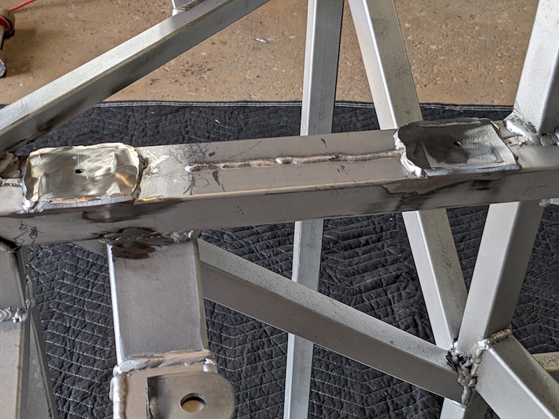
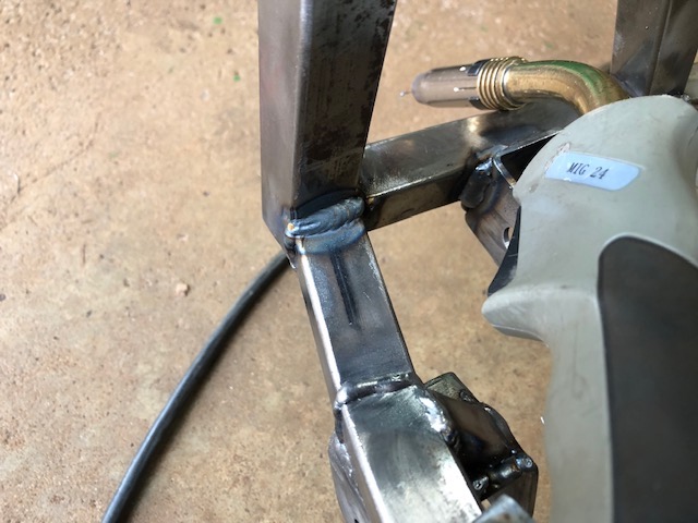
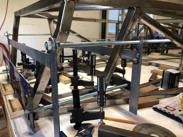
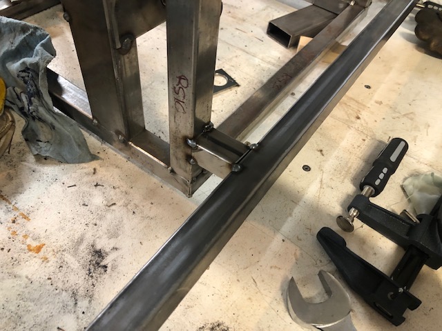
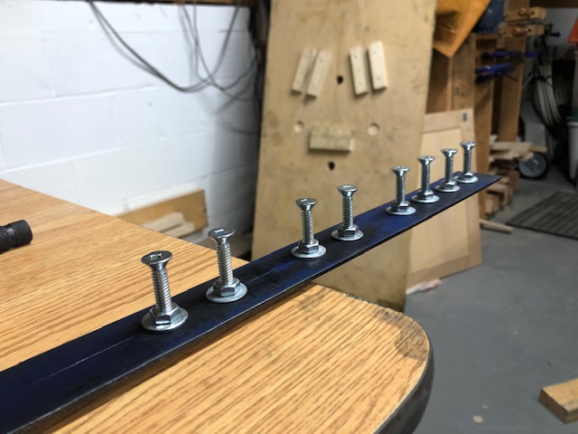
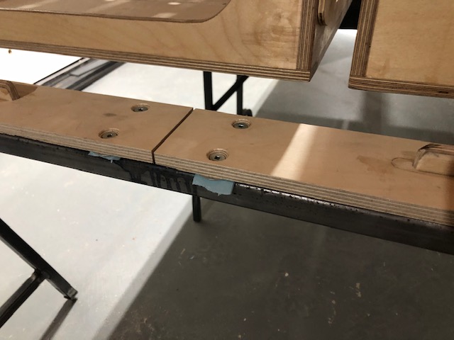
The basic setup for aligning the suspension brackets. The rigs are in place with 7/16″ (remember that) threaded rods though them and the brackets. Nuts and washers are used to keep everything from flopping around.
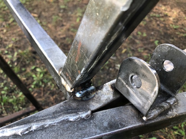
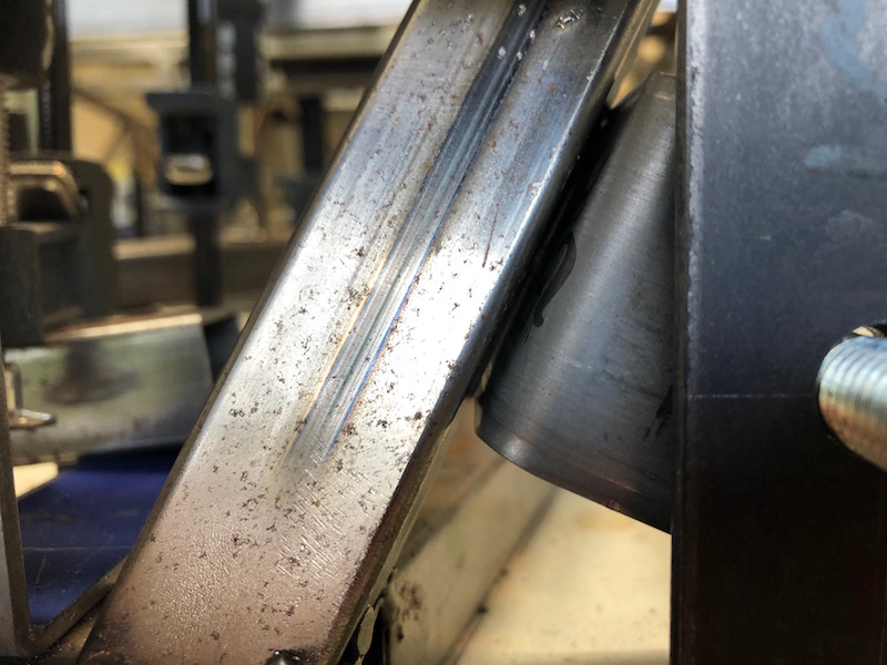
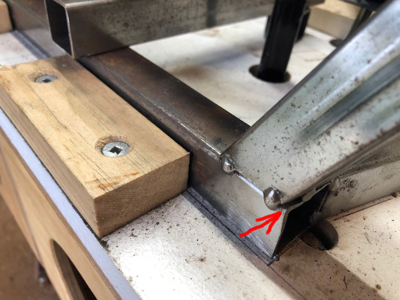
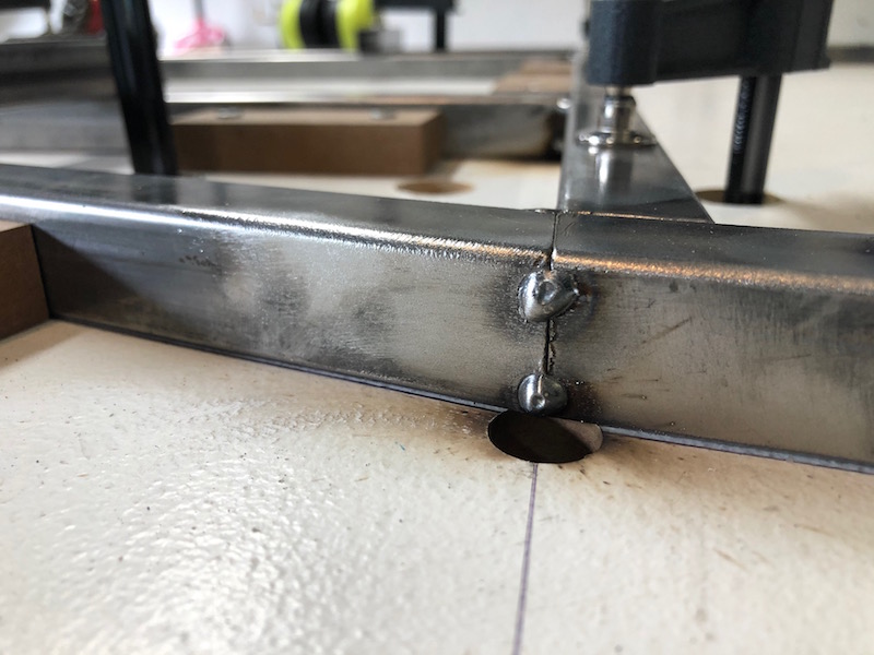
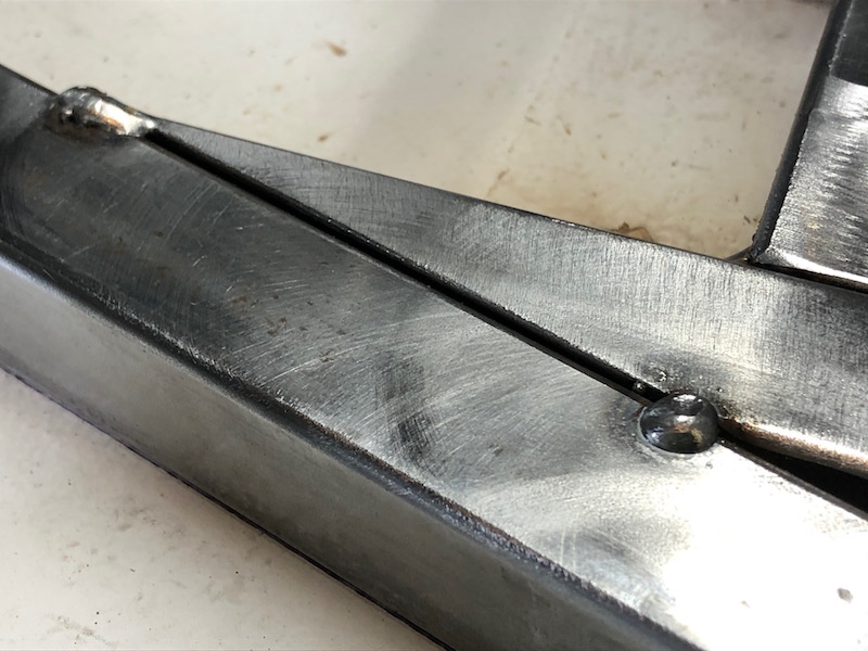
The brackets should be flush against the frame tubes. This is not the case, you can see a small gap between the front of the bracket and the front frame tube. That gap could be bridged when welding but I would rather figure out what is going on and make adjustments for a better fit.
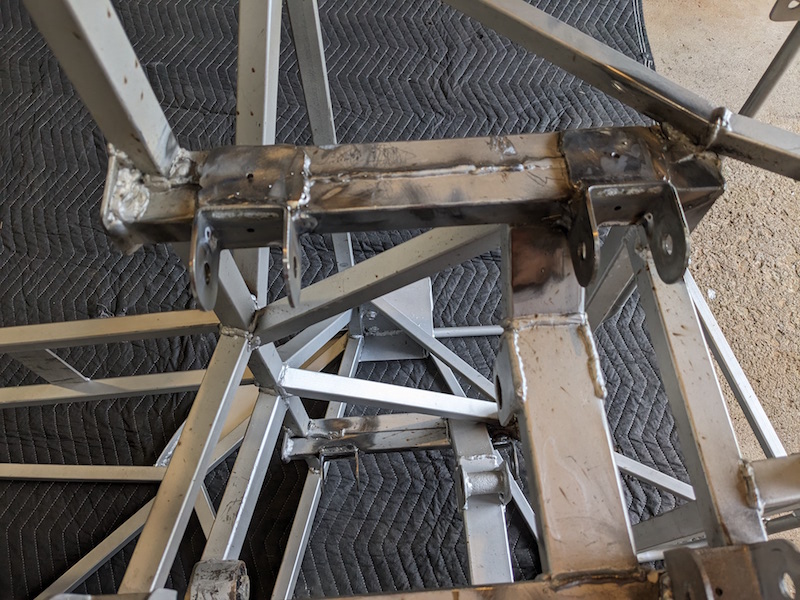
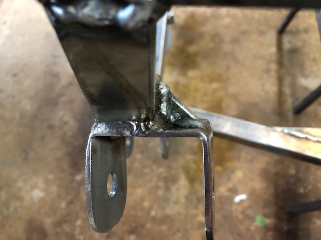
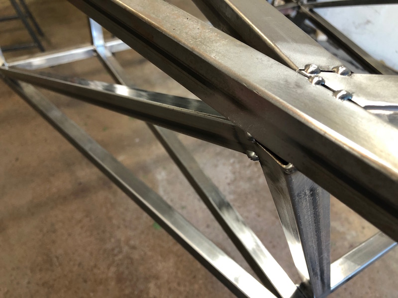
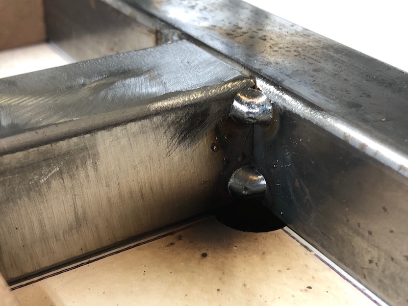
The problem is still with the front frame. Little things make a difference, that small misalignment on the bottom joint (left picture) is a big contributor to the problem. The passenger side also had a small issue. Time to grind the tacks and perform reconstructive surgery. The driver side remained attached and was tweaked into line using a 1-1/8″ wrench. The passenger side came out and was re-positioned and tacked back in place. With all the brackets and tubes nicely flush they were tacked in. Now my other problem became apparent…
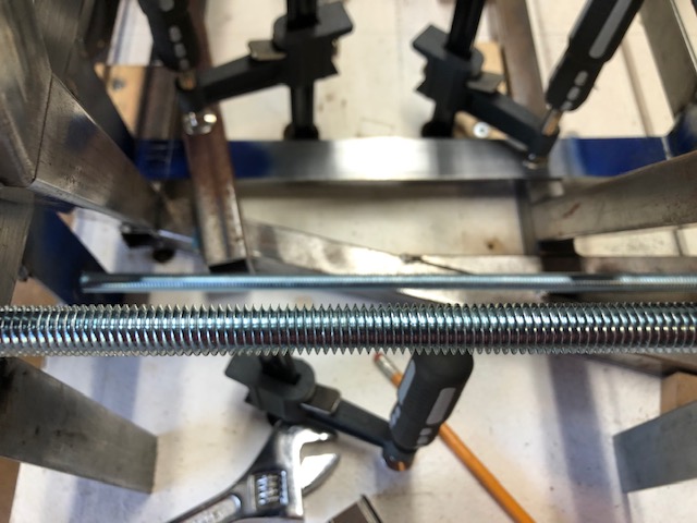
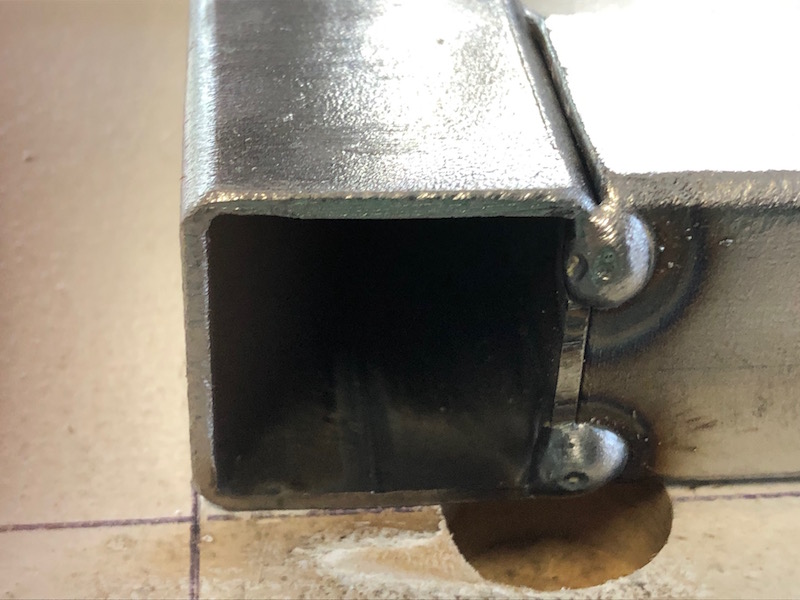
… using 7/16″ threaded rod to line up the brackets through their 1/2″ holes. This is too loose (see photo below) and provides opportunity for the bracket pair to be misaligned with one another. After they were tacked in trying to slide the 1/2″ threaded rod through was not successful on all of the bracket pairs. The book provides a bit of wiggle room by having slightly oversized holes in the locating jigs not between the threaded rod and the bracket holes. In hind sight, this makes a lot made more sense.
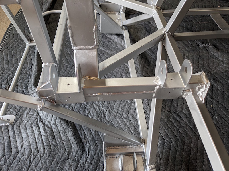
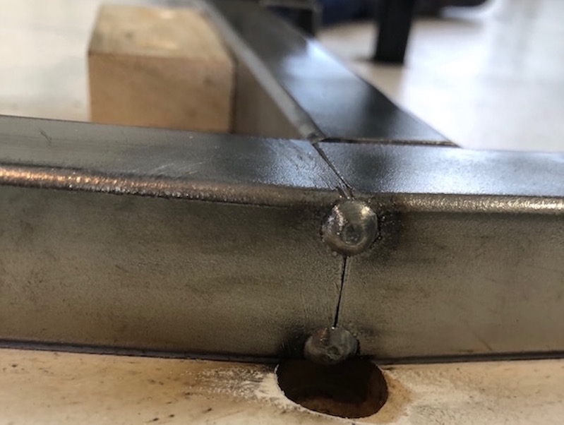
The solution was to grind off the tacks, set up the jigs again and reposition the brackets using 1/2 inch threaded rod. This went pretty quickly as in “when you do something enough times you get faster at it”. With everything tacked in I was able to use 1/2″ round bar to successfully check the alignment of the bracket pairs. The round bar is a much tighter fit though the 1/2″ bracket holes than the 1/2″ threaded rod. Now I’m happy with the alignment.
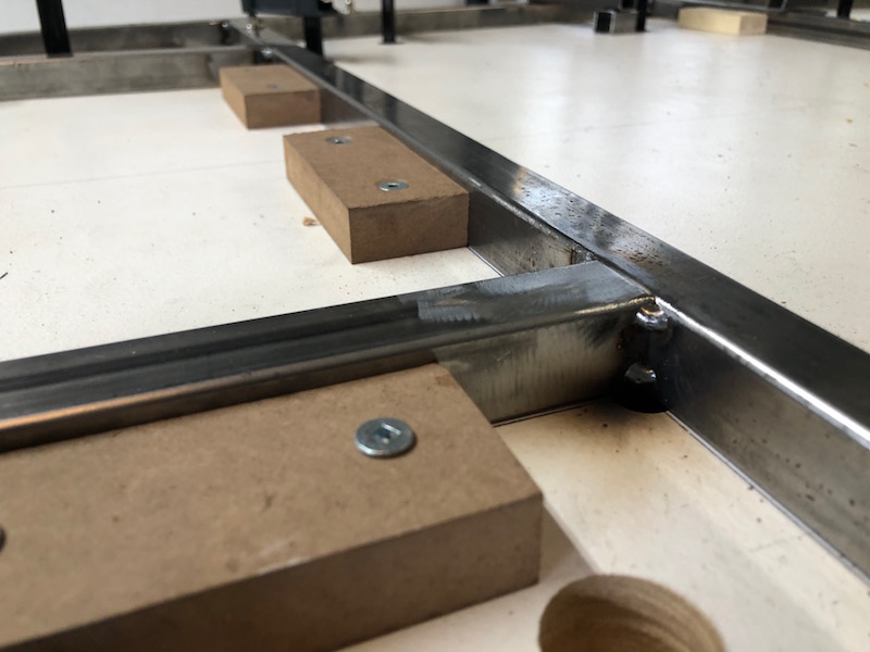
The front shock mounting brackets also need to be tacked onto the frame. They are lined up using a 1″ tube clamped across the frame. No drama at all.
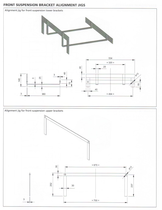
In order to position the front suspension brackets you need to make a few rigs or jigs. One for the lower brackets and two to position the upper brackets.
When the brackets are attached to the car the holes through each pair of brackets need to be inline. Also the two pairs of brackets on each side should be on parallel lines so the suspension will work smoothly. These rigs help achieve that.
Making the lower suspension bracket jig. I used the hydraulic press to bend both brackets at the same time, half the work and they are bent exactly the same. Clamping and tacking the cross pieces.
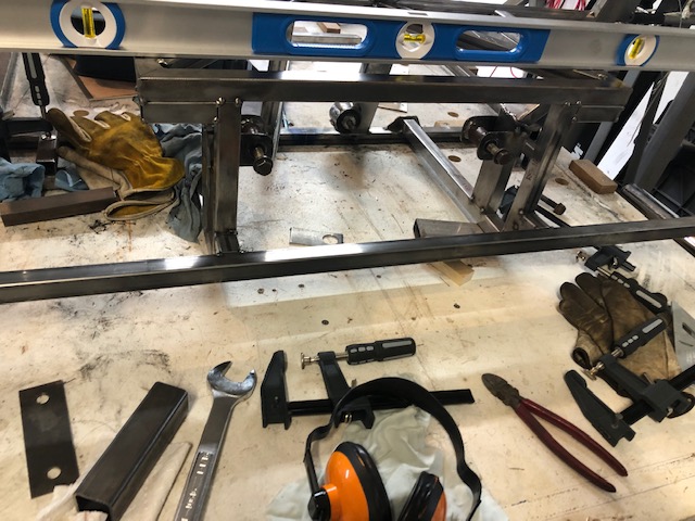
The upper rigs are just flat bar and go together quickly. Here the upper and lower jigs are in position with threaded rod through them. The rods look parallel from the overhead shot on the right. Now we need to make more brackets.
I actually made two sets of suspension brackets because I didn’t do a good job on the first set. I used the dimensions in the book but think I took off too much material rounding the ends. On the second set I used slightly wider material 1-3/4″ (44.5 mm) vs the 40 mm in the book. I also made them a little longer so I could fully radius the ends leaving more material between the hole and the edge of the bracket.
I started by welding the ends of four 1-3/4″ wide 4′ lengths of bar together. Now I could cut blanks in groups of four and not have to worry about the bars shifting. 1/4 the work!
I marked the center line, hole position, and bend lines on templates and and drilled pilot holes with a center drill. I then clamped up the blanks in sets with a template on top, ground off the corners and welded them together.
Now I could drill through the stack of blanks without fear of them shifting. After I had the 1/2″ holes drilled I marked the radius to grind, bolted the blanks together and cut the corners off with the angle grinder and cutting wheel. Next I ground the radius with the flapper disk. Remove the bolts and the blanks are ready for bending.
I spent a lot of time aligning the punch with each blank. There is enough play in the press that the tool does not remain in a consistent position from piece to piece. I had scribed a line down the sides of the blanks marking the bend lines while they were bolted together. The point of the punch was aligned to that mark. You can just see the mark on the side of the blank if you squint.
The end results are very good, here are eight of the brackets on a 1/2″ threaded rod, all holes aligned very nicely. The right picture shows one of the brackets from the first batch with the new beefier version.
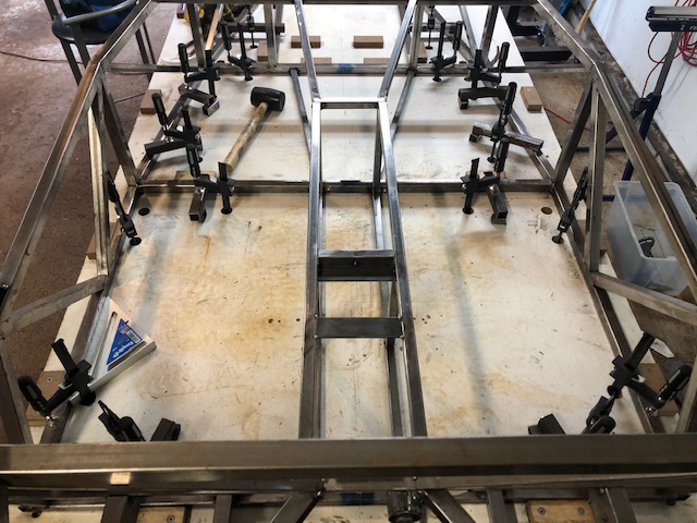
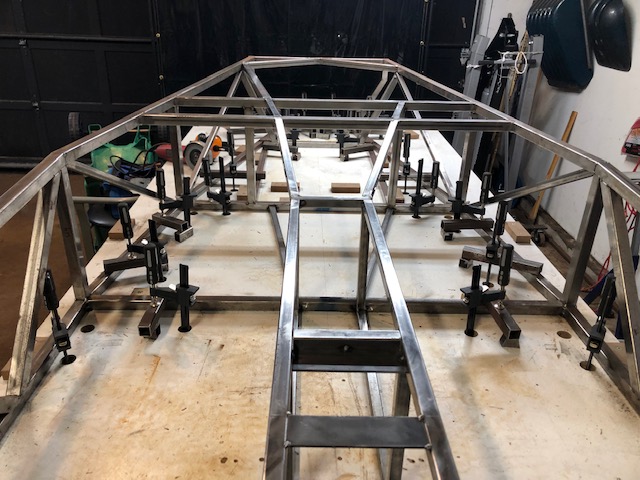
It’s time to put in the transmission tunnel. Just like the frame, it starts by cutting and tacking the tubes that lie on the bench. We then work our way up. This went pretty quick.
At this point I moved a couple of the front tubes that were intended for a right hand drive car. It is now a left hand drive frame with more room in the driver side foot well.
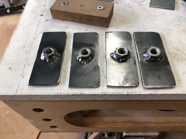
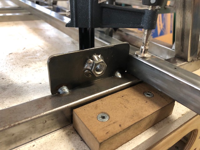
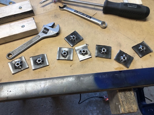
It’s time to install some safety equipment – the lower seat belt attachment points. Nuts are fully welded to the back of the plates and they are tacked onto the lower frame rails and the transmission tunnel tubes.
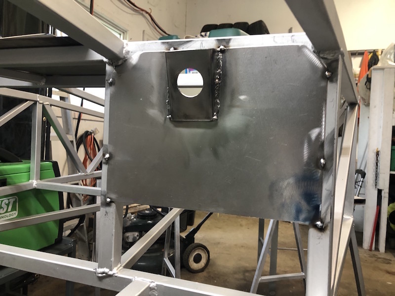
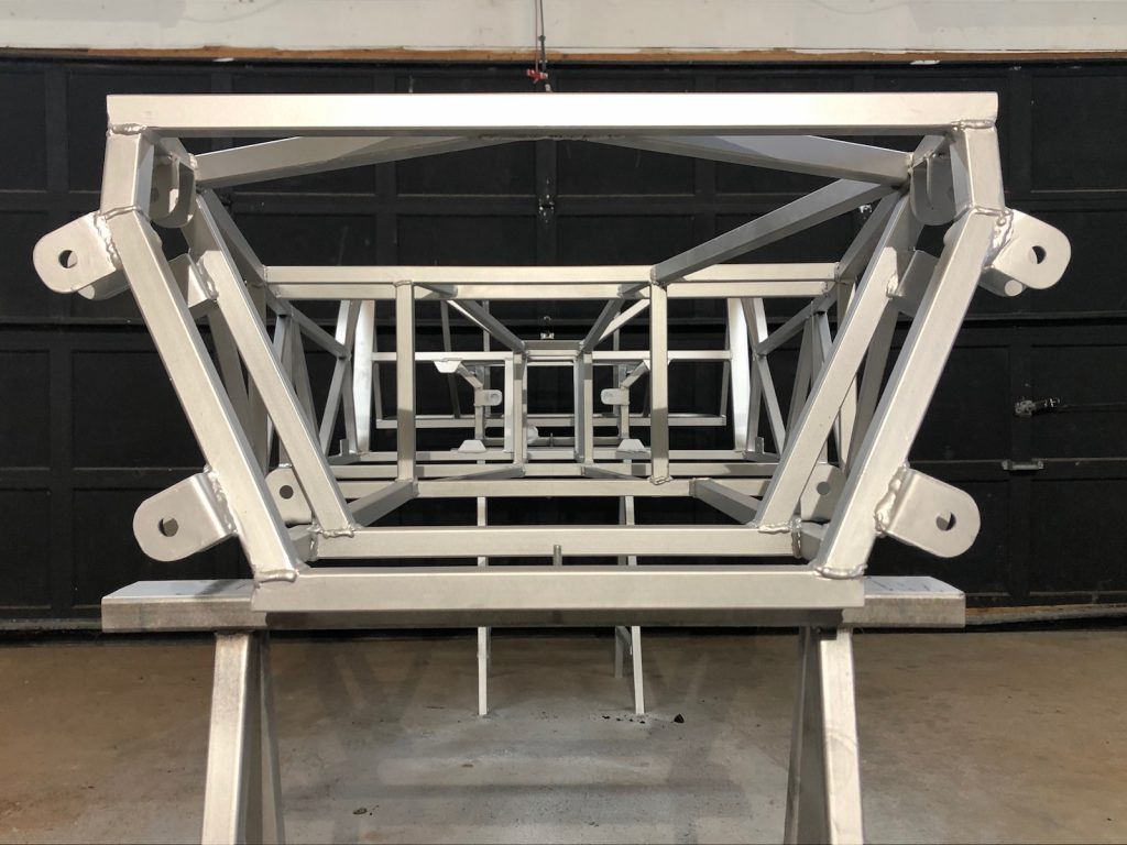
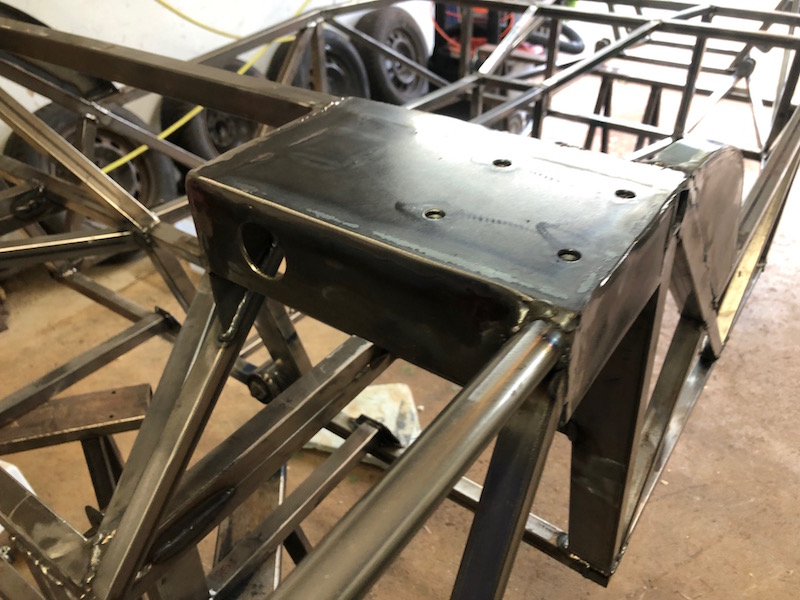
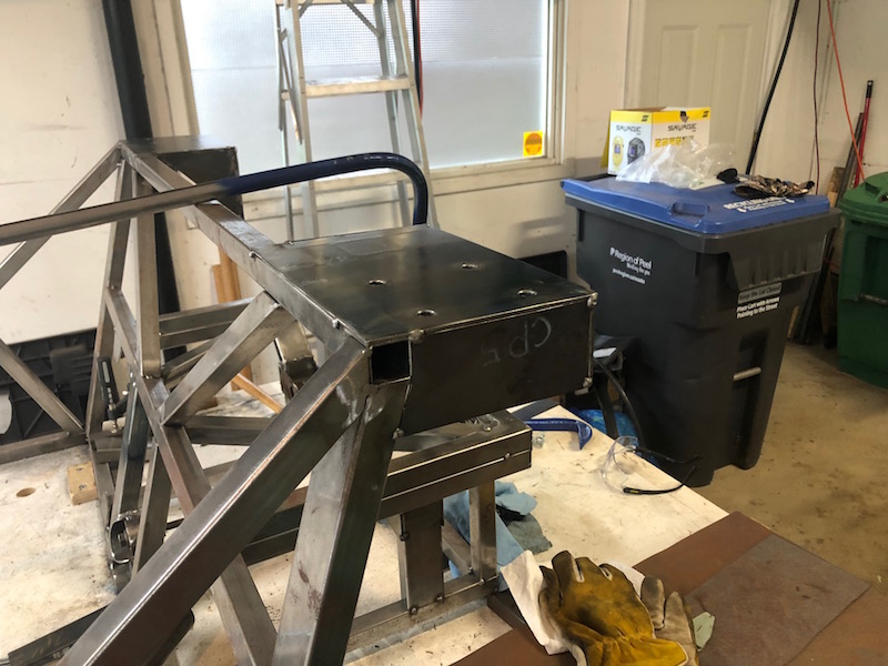
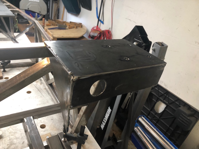
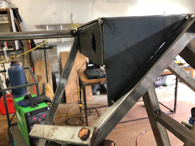
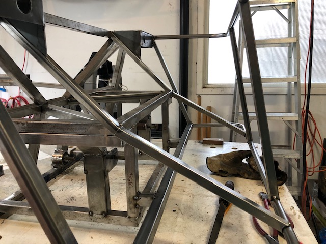
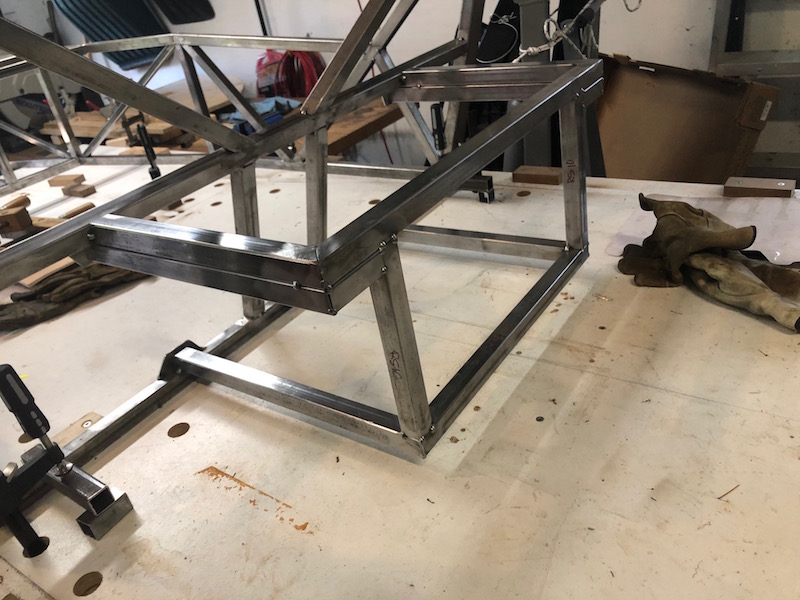
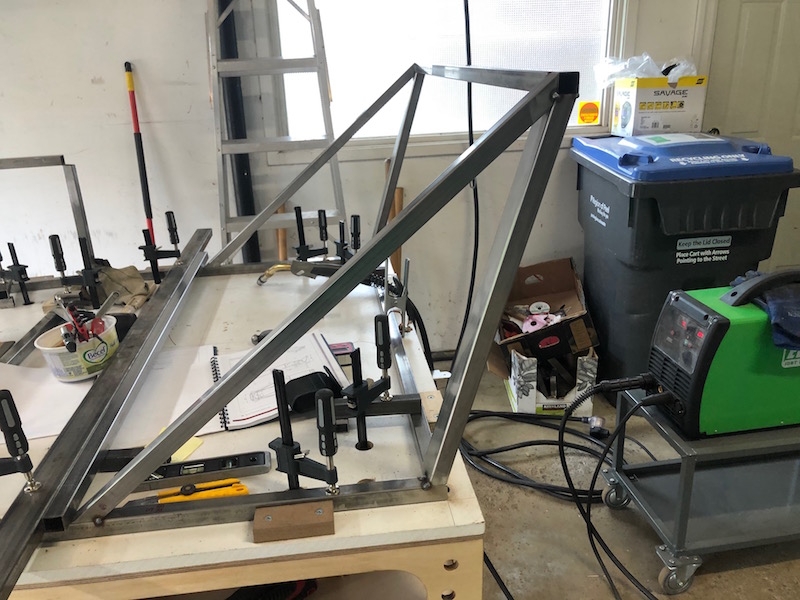
The next step in building the back end framework is to fabricate the plates that the roll bar mounts to. The shock absorber bracket mounts on the bottom of this plate and needs to be fully welded as access is limited after the back end is done.
4 nuts get welded onto the underside of the plate for the roll bar and the shock bracket gets fully welded.
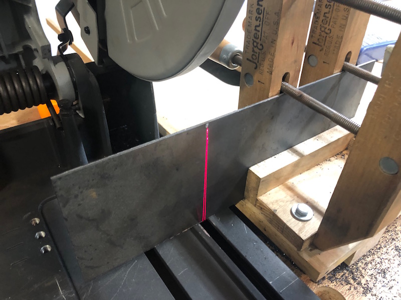
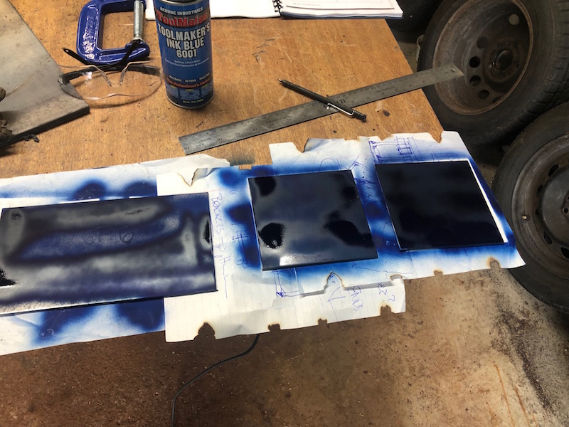
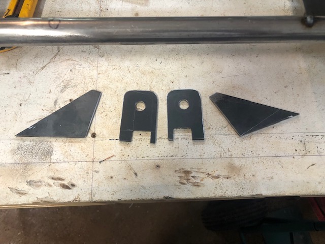
Next we need to fabricate the 1/8″ plates that box in the sides of the roll bar mount. Everything gets cut vertically in the saw, painted with machinists blue and marked before cutting. If it can’t be done in the chop saw then the angle grinder and cutting wheels are used.
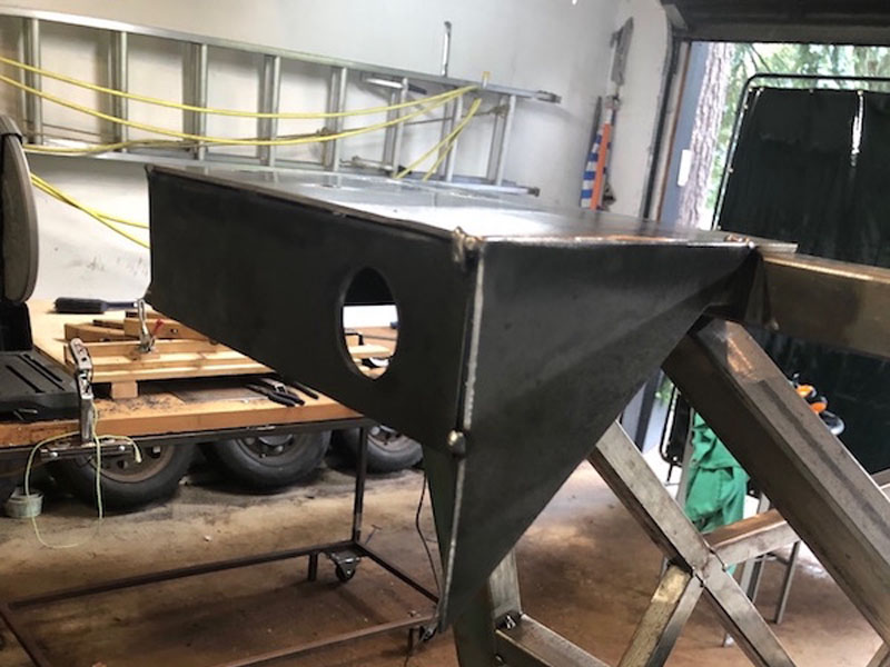
The roll bar plates are tacked onto the frame and then the sides of the box get tacked on around them. The 1″ hole in the back plate is to allow access to the top shock mount bolt.
A lower cross tube gets attached to the back of the suspension box and a diagonal support tube for it is tacked in (no picture – sorry).
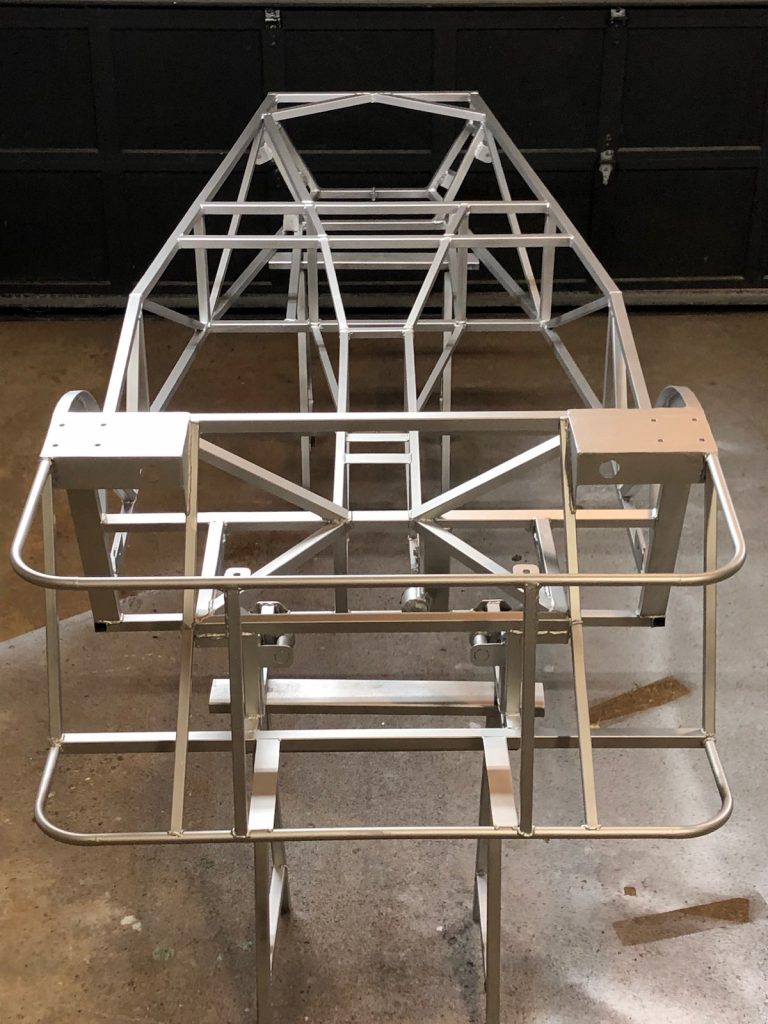
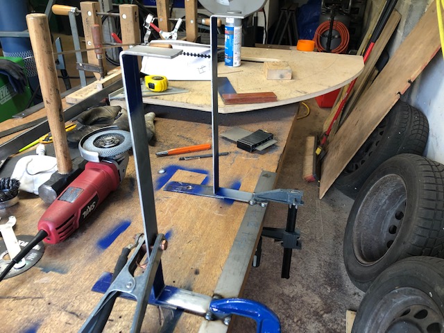
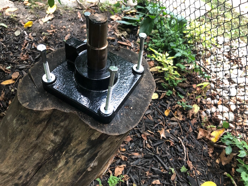
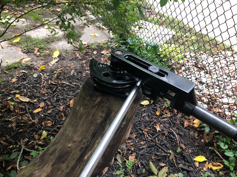
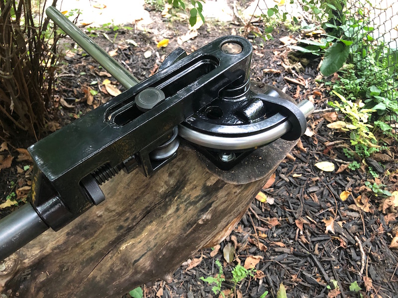
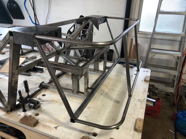
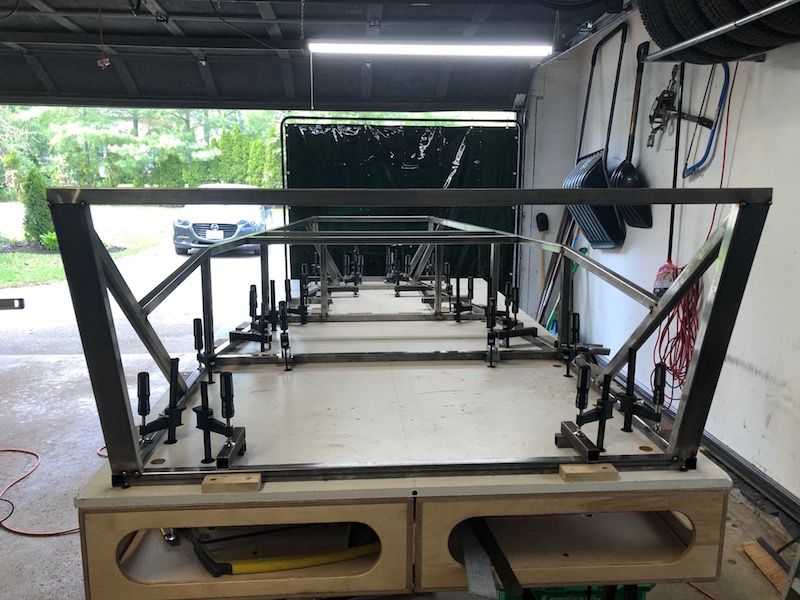
Now we need to bend some 3/4″ round tubing to form the back of the body work. We will be using the tubing bender that I bought at Princess Auto (on sale of course). Bending tubing requires putting a lot of force on a long handle so the bender must be solidly mounted. Normally a sturdy steel post would be fabricated and bolted to the concrete shop floor with the bender mounted on top. That’s a lot of work so I opted to lag bolt it to the top of an old tree stump in the back yard. I had cut down the apple tree several years ago and the stump was high enough to be workable and it was still very solid.
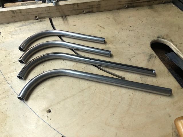
The bends were nice and smooth, no kinks or ripples. A framing square was used to align them and tack them to the straight lengths that would connect the two sides.
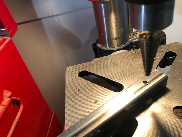
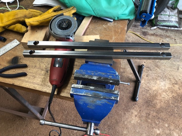
Next 3/4″ struts that connect the two round rear body frames need to be made. I cut two pieces of 3/4″ tubing longer than needed. I then used the stepped drill to make a large hole in each end the correct distance apart. A quick trip to the chop saw and the struts were ready.
Here is everything tacked in place.
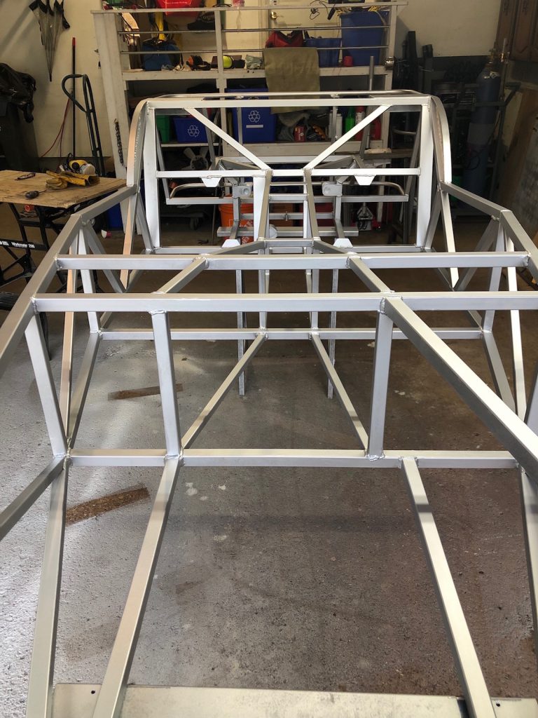
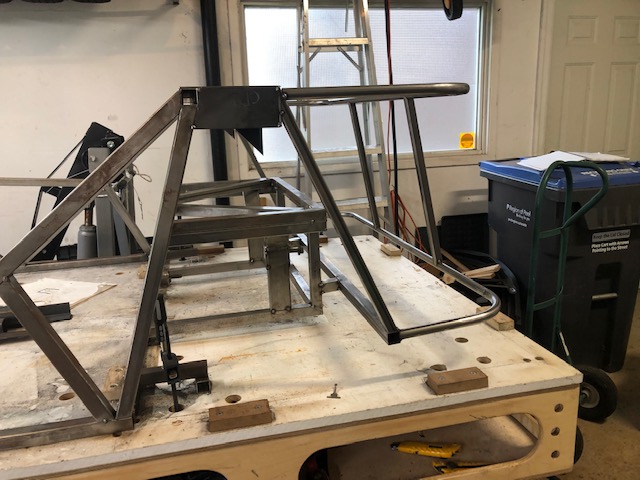
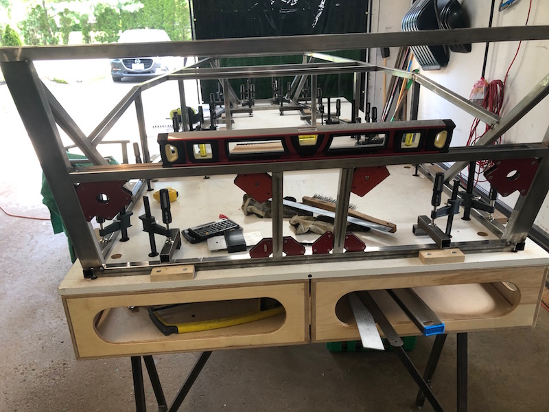
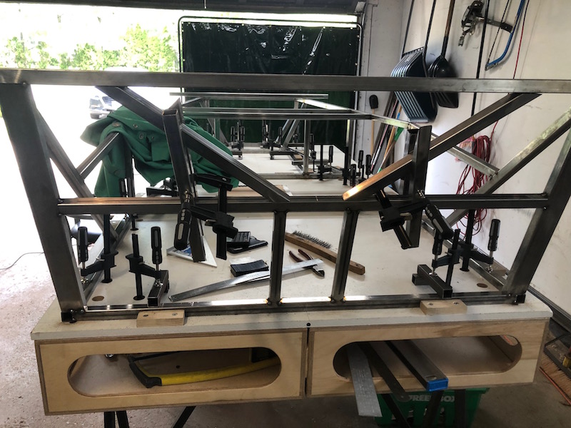
Now the rest of the back end framework needs to get put together. Diagonal 3/4″ tubes run along the triangular edge of the roll bar box down to the top corner of the suspension frame and on to the lower bodywork tube.
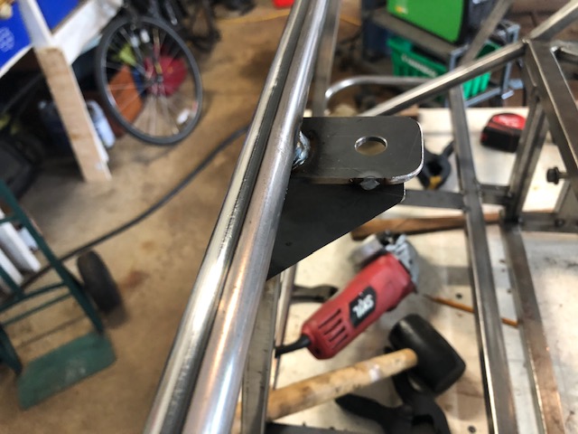
The roll bar will have a couple diagonal stays that go from the top of the bar down to the top round body work tube at the back of the car. These are the brackets that get tacked on for the stays to attach to.
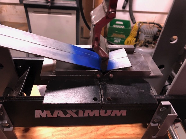
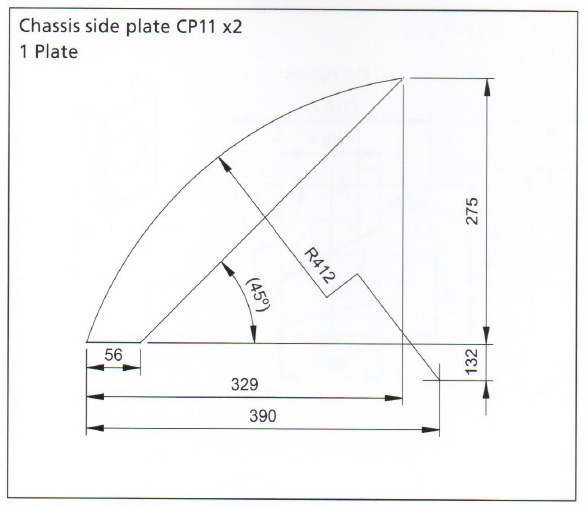
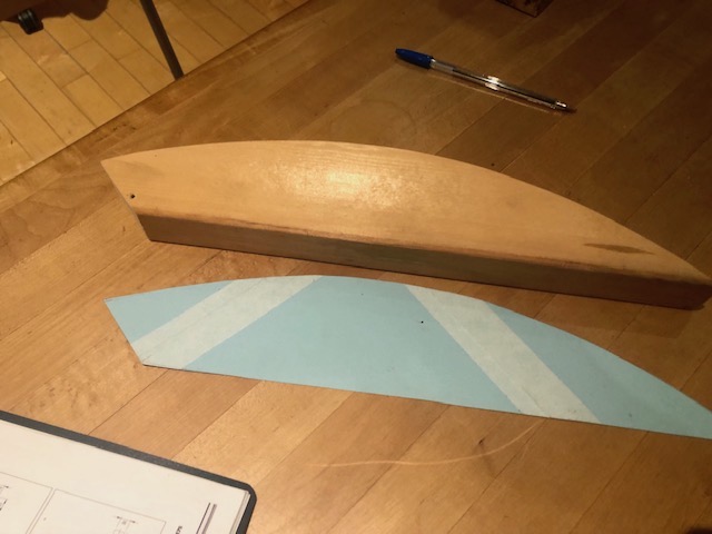
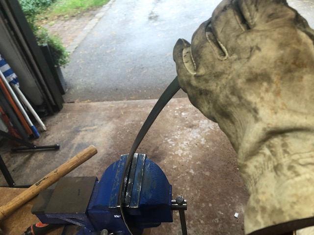
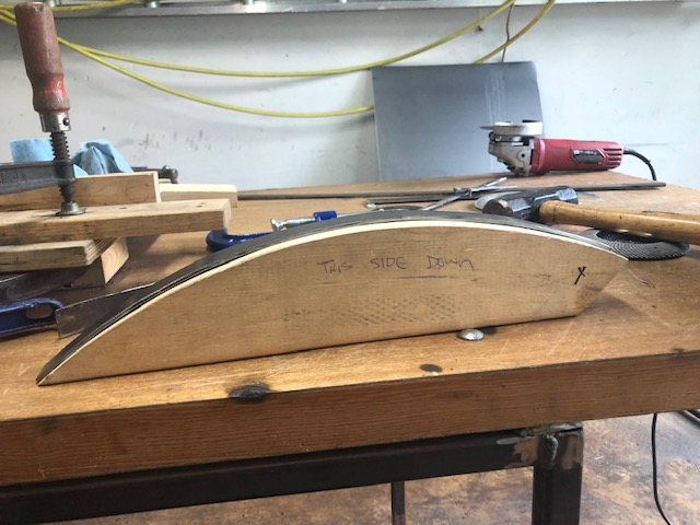
Finally, a couple chassis side plates need to be fabricated and tacked in. They are a bit of an odd size and shape and a 1/8″ thick plate needs to be bent to match the profile of the curve. I created a paper template and cut a wooden buck out of a piece of scrap 2″x6″.
The wooden buck wasn’t useful to hammer the steel on but it was great for checking fit as I shaped the bar. I found that the best method was to put the bar in the slightly loose vice jaws and bend gently. I could work along the length of the bar by putting it further and further through the vice. I checked the fit as I went and eventually I had a very nice match.
Cutting the plate was straight forward. Trace the buck on it, cut it out with the angle grinder, and then grind the edge smooth.
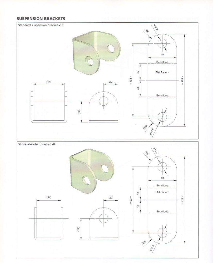
We need brackets in order to proceed. There are 8 shock brackets and 16 suspension brackets used in the build. The shock mounts are needed to fabricate the back framework of the car. It is possible to buy brackets but what would be the fun in that? This is another opportunity to use that hydraulic press.
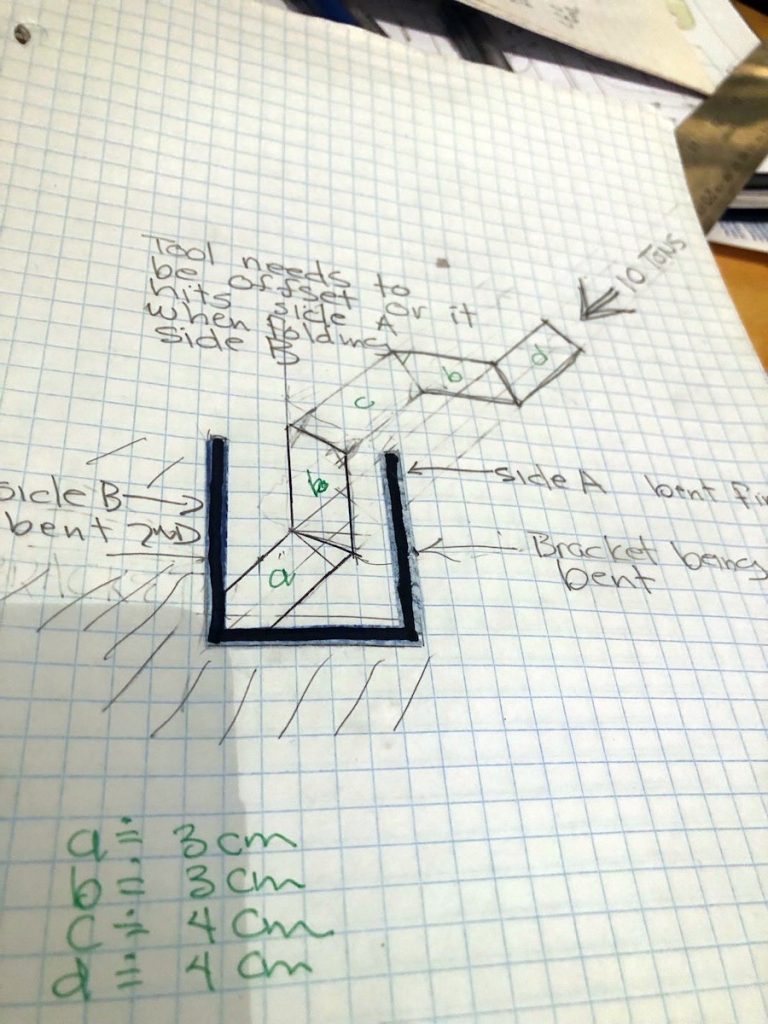
In order to make U shaped brackets we need a “press break”. The break has two parts, a punch and die and in our case they will both be 90 degrees. The punch is forced into the die pressing the metal to be bent forming a right angle. Now we have “L” shaped brackets. Then we put the straight end of the “L” on the die and press it to form a “U” shape. The punch will need to have an offset so that the second fold does not cause the first folded side to interfere with it. This is another of my detail “design drawings” that shows how the punch needs to be shaped.
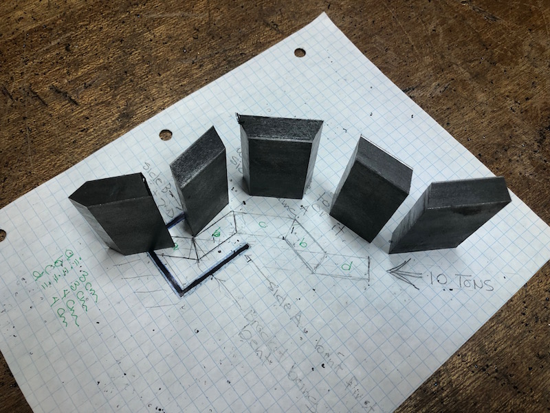
The punch was made from 1/2″ steel. The chop saw cuts it easily, the parts were cleaned up with the angle grinder giving the edges a bit of a bevel so hopefully the weld penetrates better.
After it was fully welded I made a collar to attach it to the hydraulic cylinder and welded that on.
I had a couple different dimensions of thick walled square tube and thought I could make the die from that. It also gave me more practice welding. Once that was done I put a test bracket in the press to see if it would work.
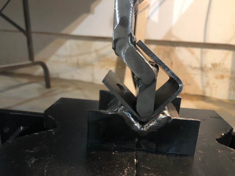
Bending both sides of the bracket. You can see why the offset is needed.
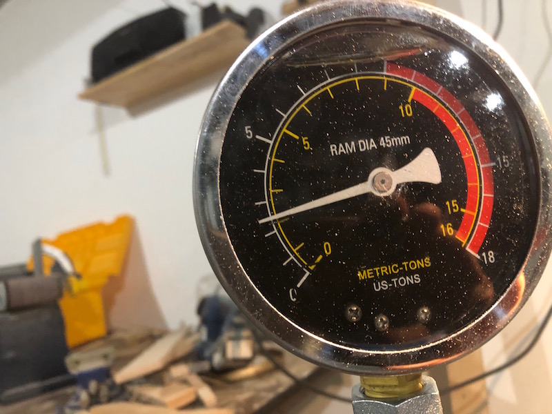
This worked surprisingly well, the 1/8″ steel folded like paper in the press. There was negligible pressure on the hydraulic gauge until the punch bottomed out in the die. When that happened I pumped the press handle and put about 2 tons force into the die. The result was that the bends were a bit over 90 degrees. The bottoming out pressure really seems to set the angle, too little and it is a bit under 90 too much and it is a bit over. Some experimentation required.
The two dies that I made would not be useful for producing all the brackets needed. There was no way to easily position blanks on the die consistently in order to get repeatable results. I would have to make a better die.
I did some Google research and found that having the throat width of the die equal 8 times the material thickness being bent is ideal. Since I was bending 1/8″ material a 1″ throat would be needed. Math reared it’s head again, I still had some 1/2″ thick bar and cutting 45 degrees to make the die would make a throat width of exactly 1″. The chop saw did it’s thing and this time I just tacked the plates together. The flat bed allowed me to clamp a stop block down and position the blanks consistently.
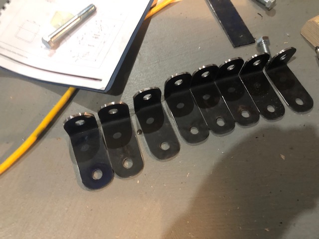
I made up the 8 blanks for the shock mounts and used a template to drill pilot holes in each end before drilling them to 1/2″. I then bolted them all together and used the angle grinder to round the ends. Now I unbolted the blanks and started bending.
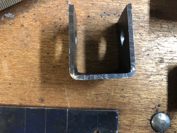
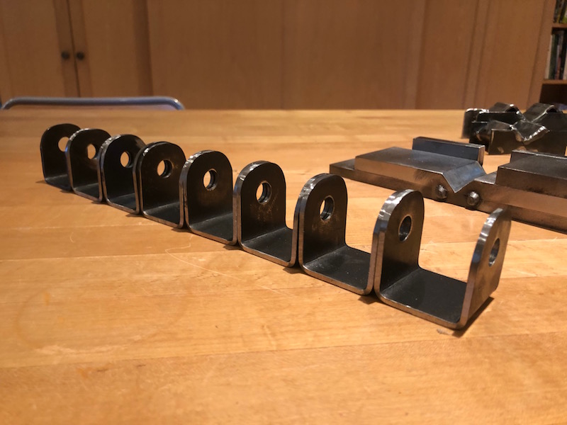
Half way done.
The finished product.
That worked out great. I have some ideas to improve my bracket production process that I will try on the suspension brackets. Now I need to get back to the car frame, the suspension brackets can wait till they are needed.
Tom, Melissa and their two dogs Charlie and Louie are in town for awhile waiting for their new house in NB to be completed. Now I have more help with the car! We have shifted the frame forward on the bench to build the back end.
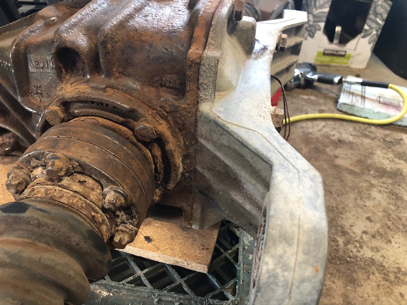
Now that the differential is free we put it in place to see how it fits. There is some interference with the passenger side upright at the back of the transmission tunnel. Other than that it looks like we can build the back end as per the book.
Proceed!
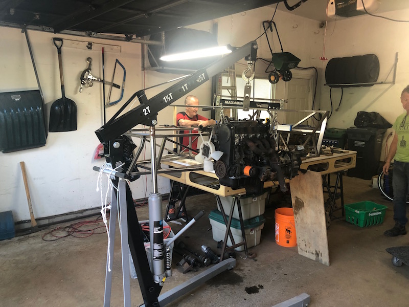
Paul came in from Barrie and we had a session to see how the motor might fit. We hung it in position beside the frame with the engine hoist to eyeball things.
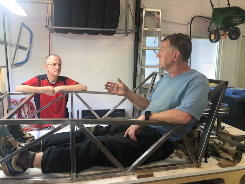
While we were at it, we decided that we should see how we fit in the car. Paul fit best and Tom refused to get in. A fun time was had by all.
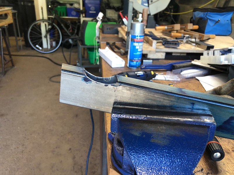
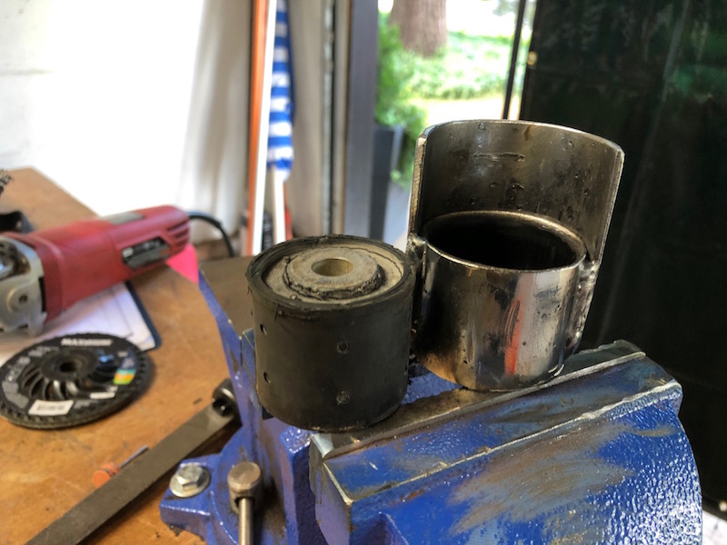
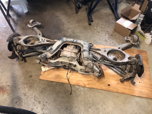
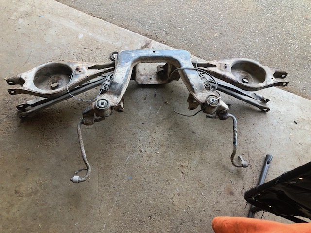
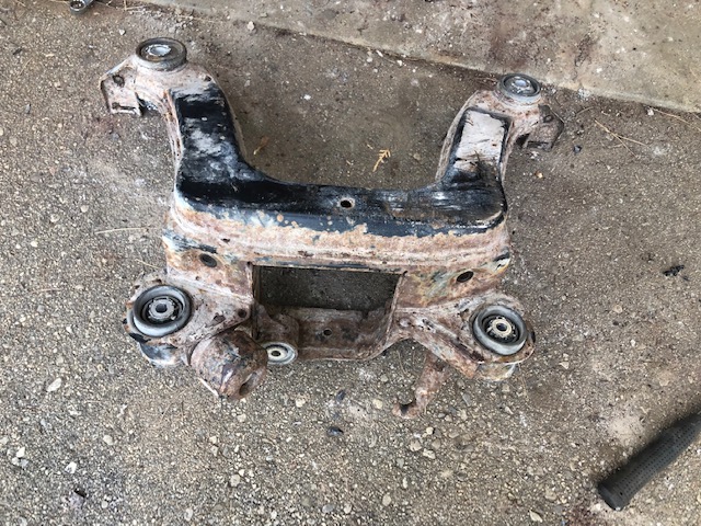
Back to the build. On the left is the sub-frame that held the differential in the BMW. I cut out the three connection points that attached the differential and plan to reuse them. On the right are the connectors from the sub-frame along with some bits I made to attach them to the Locost frame. The flat plates will be used to attach the two smaller connectors that the rear of the differential bolts onto. The rounded shell started as a 1/8″ thick flat plate that was hammered by hand to fit the large rubber mount. It will support the front of the differential. It’s amazing to see how steel can be shaped with just a hammer and vise.
Two of the plates get welded onto the ends of each mount. This one is clamped down to weld the bottom plate. The plate on the top is just to provide a flat surface for clamping.
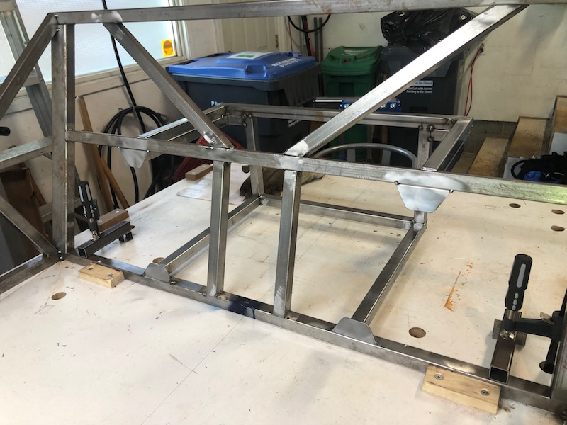
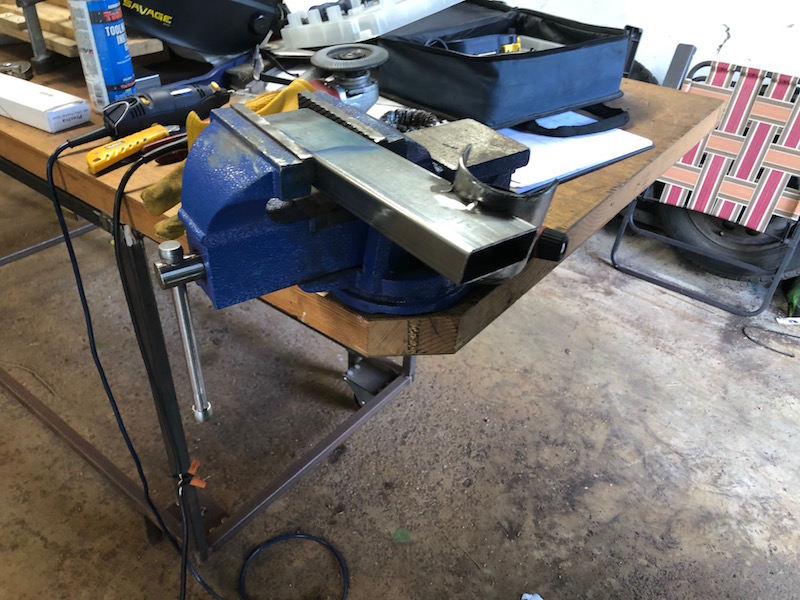
A pair of uprights were made to connect between bottom frame to the side of the double top frame. These would hold the pair of back mounts for the differential.
The differential was blocked up in position and the rear bolts put in before the brackets were tacked. The passenger side transmission tunnel upright has been removed because the front mount interfered with it. We will fix that next.
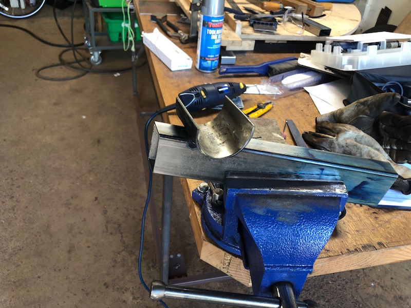
The missing 1″ upright will be replaced with a 1″x2″ upright that needs to be notched to accommodate the front mount. Once the shell fits properly the front mount tube is welded onto the shell.
Now the shell and mount can be tacked onto the upright and then fully welded. The excess shell was trimmed with the angle grinder. The rubber mount can then be pressed back into the tube and with the differential in place the upright can be tacked in place.
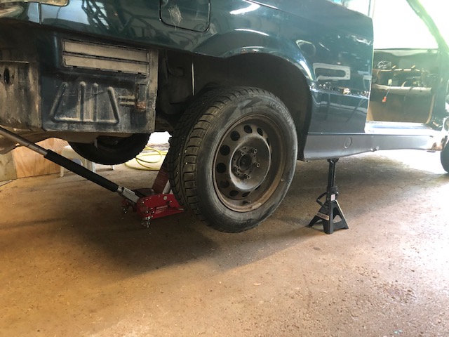
Paul and I had a good chat about donor vehicles and came up with one manufacturer that resisted the FWD trend and whose cars were fairly affordable: BMW (Break My Wallet). I was able to find a 1995 318i Cabriolet that was being parted out by a young fellow. By the time I got to it it was pretty much gone, but the suspension was intact and that’s what we needed. I bought it and had it towed home.
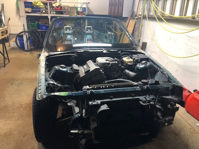
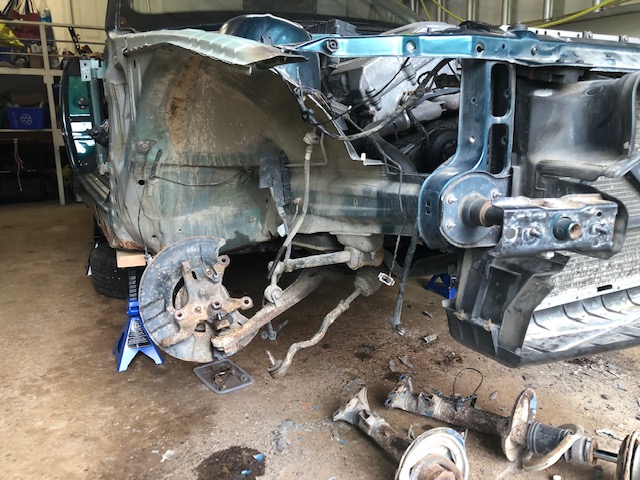
The engine and automatic transmission were still in the car but we wouldn’t using them. Let the dismantling begin.
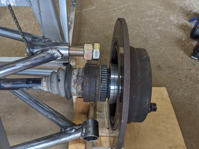
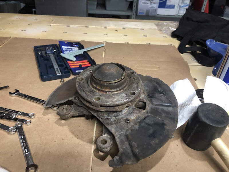
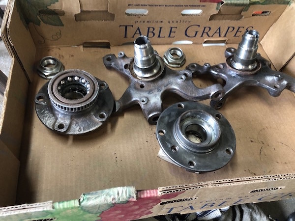
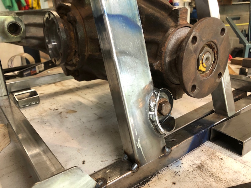
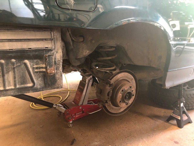
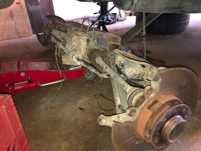
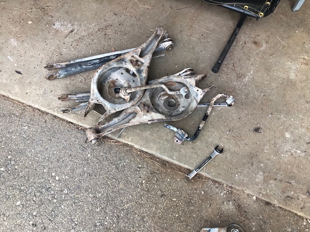
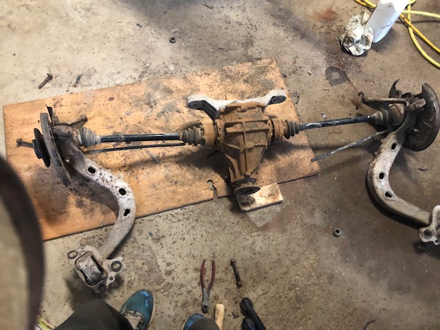
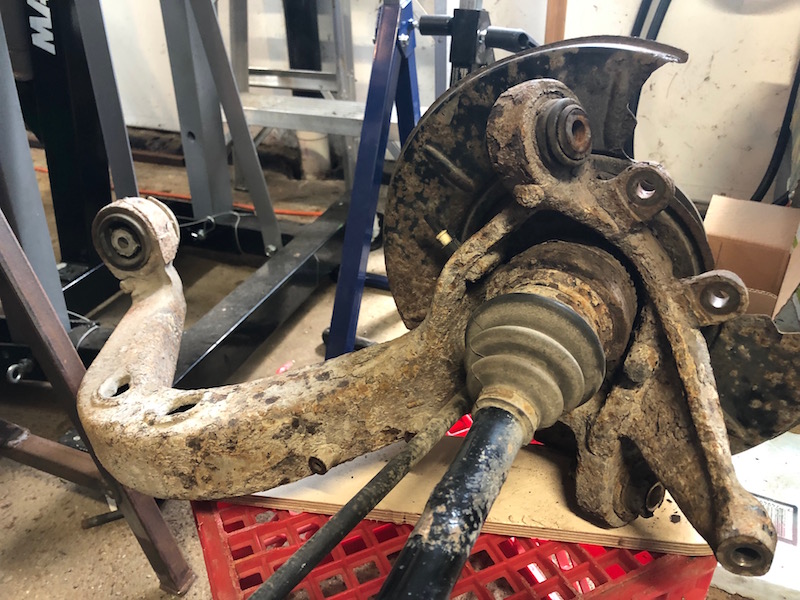
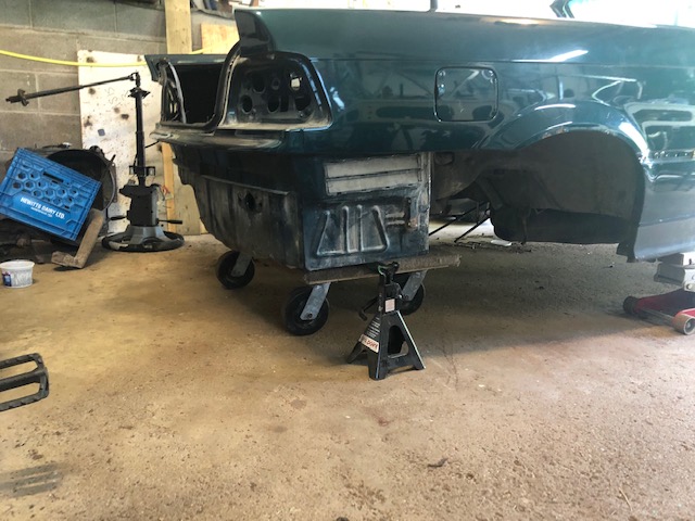
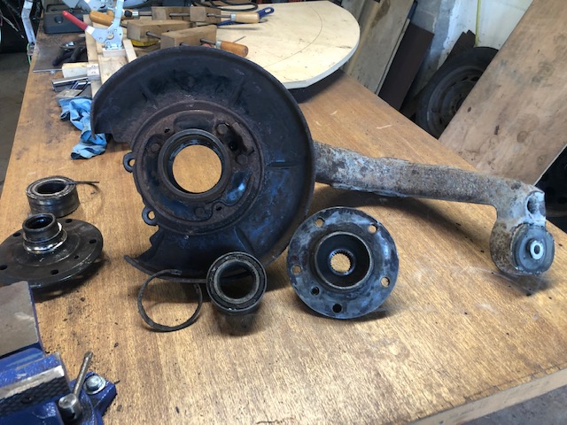
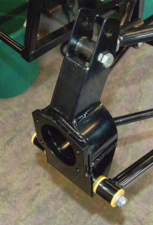
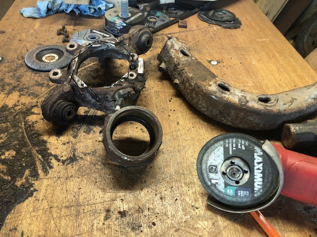
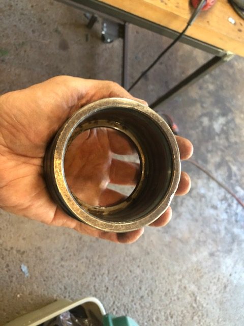
Here is one of the rear hubs, it is a large steel casting that does a lot of things. It holds the bearing that the end of the half shaft passes through (outside the CV joint) to drive the rear wheel. It also mounts the brake caliper, the control arms and that curved piece ties into the car frame to allow the rear suspension to travel up and down but not front to back.
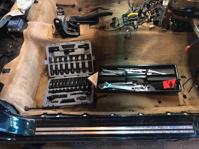
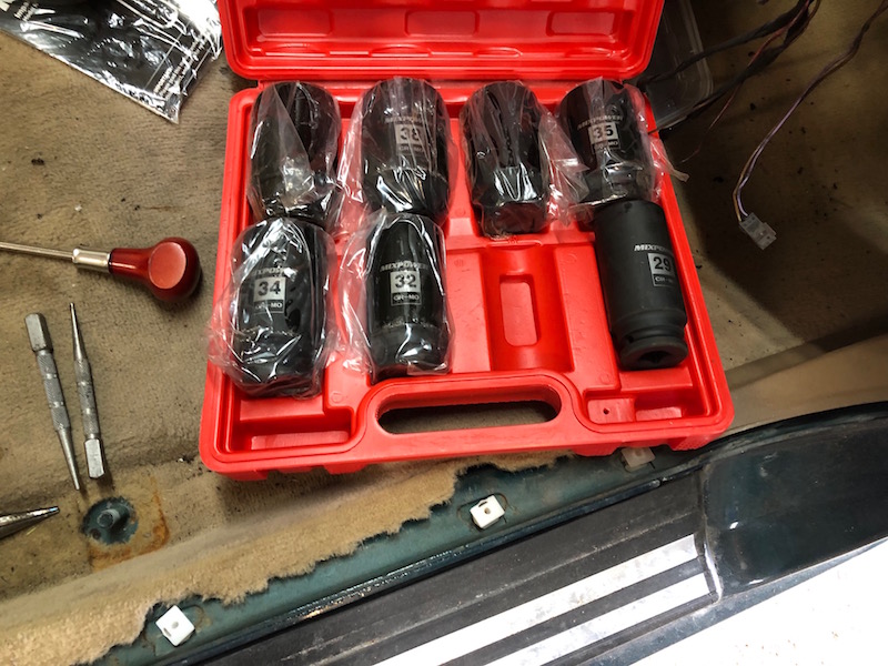
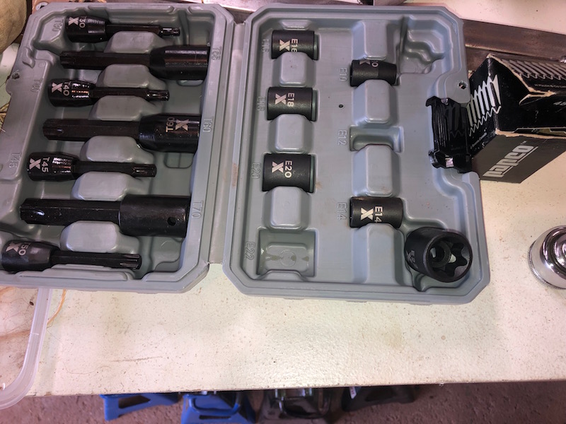
I swear that BMW and Canadian Tire are in cahoots. Every time I go to take something apart I need another tool or a different type of socket. This is the 12 point 30mm nut holding the hub on, beside it is the beautiful new set of sockets. At least the hub is off.
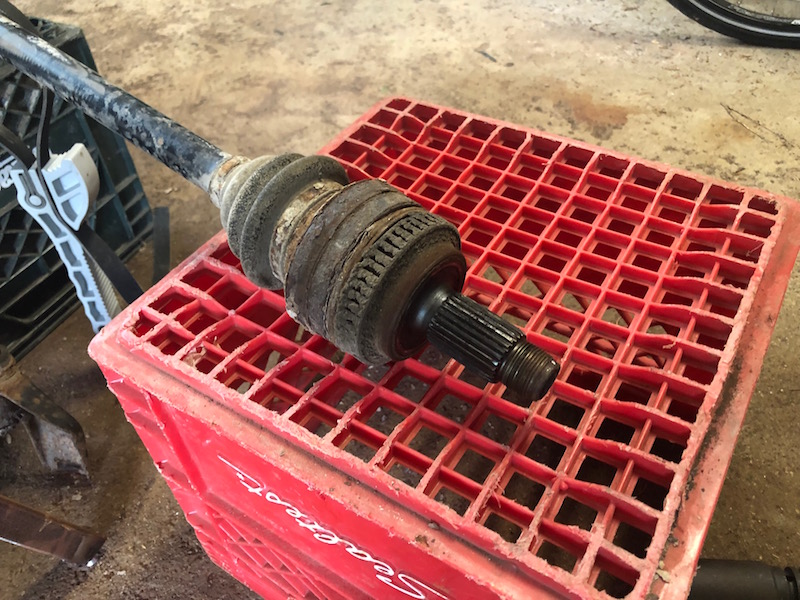
Oh, and those are Torx head bolts (of course) holding the half shaft onto the differential. Another trip to CTC and we are in business. I got to make use of my favorite new tool – the impact wrench!
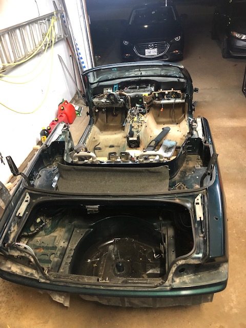
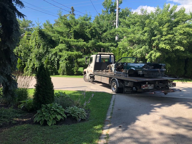
Bye Bye Bimmer. With all the useful parts left behind, the BMW is unceremoniously dragged from the garage and sent off to the recycle yard.
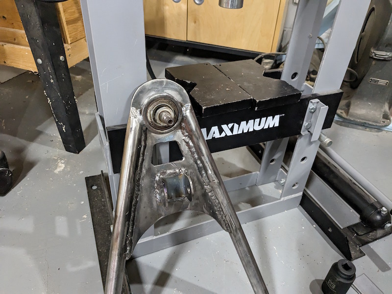
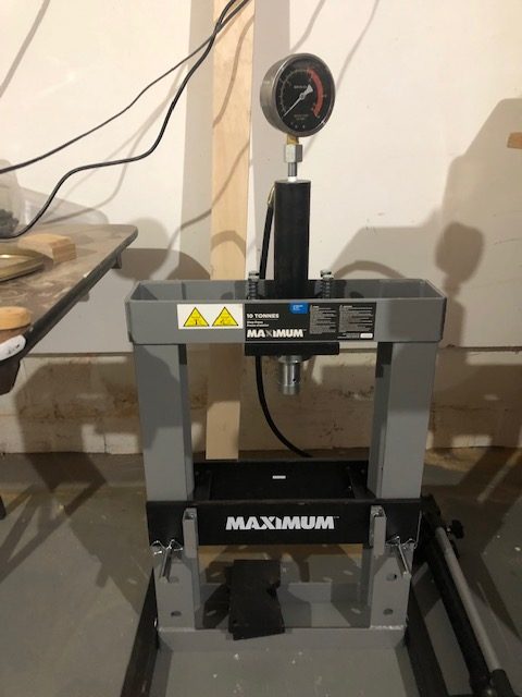
Now that the rear hubs are free of the half shafts we need to take them apart. This involves pressing the bearings out of the housing. This could be done by a local garage but they would spend at least an hour and a half doing it and that would cost a couple hundred dollars.
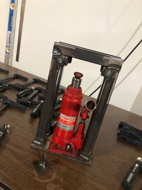
For about the same money, I can buy a 10 ton hydraulic press (on sale at Canadian Tire!) to do the job. As a bonus, I will have it to do all kinds of other jobs like pressing in the new bearings down the road! I have been trolling the Canadian Tire and Princess Auto web sites looking for tools I will need to go on sale. It is called a Locost after all!
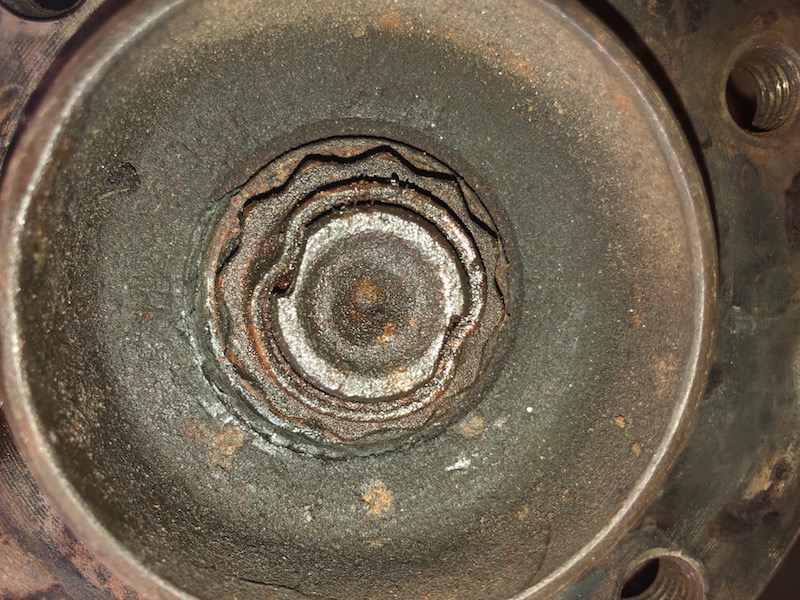
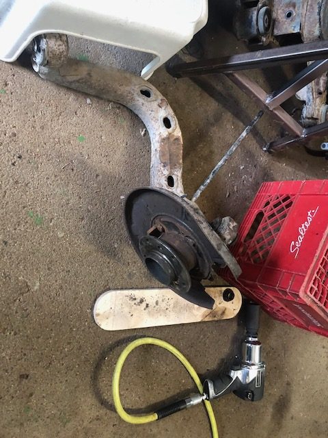
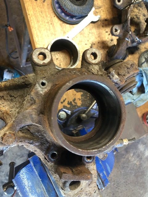
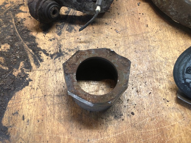
The big snap ring holds the bearing in. Once it is removed the press can be used to push the bearing out. This is a bit tricky because of the casting shape. It takes a few tons force to get it out.
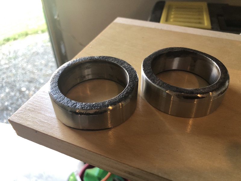
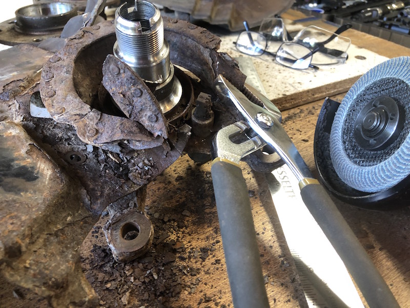
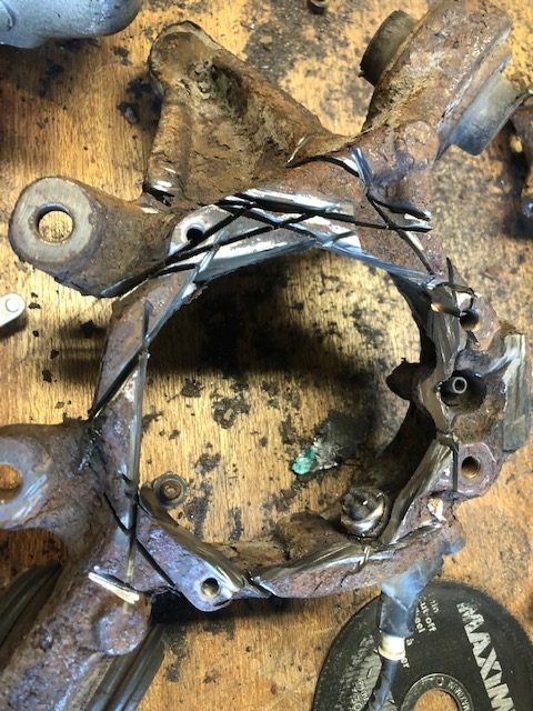
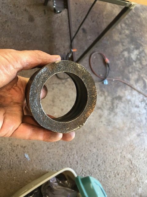
I decided to try to cut the bearing holder from hub. The plan is to incorporate them into the new fabricated rear hubs. The rest of the BMW casting will be discarded. The standard rear hub from the book will be modified to fit the E36 components.
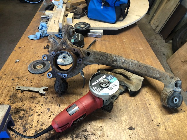
This is a slow, noisy, dirty job but it has to be done and I couldn’t talk Tom into doing it. Several abrasive disk later the job is completed. I looked like a coal miner after a 12 hour shift.
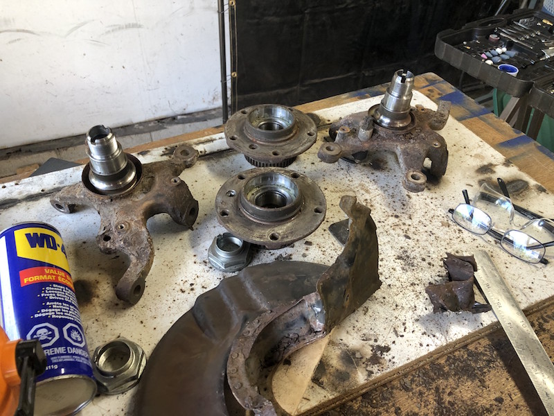
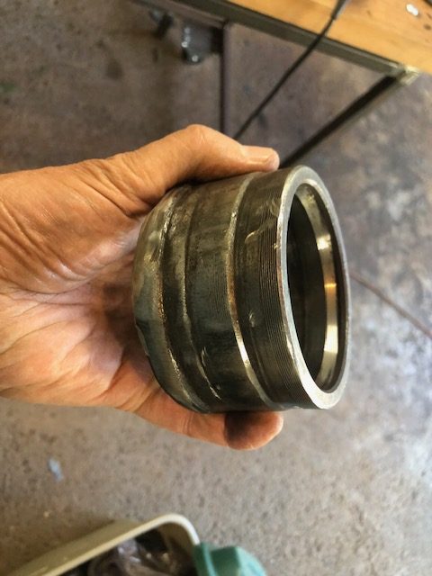
More work with the angle grinder to get the bearing holder basically round. Tom will be taking these to New Brunswick to turn them on his lathe. He will use an inside chuck so he can cleanup the outside and flatten the bottom surface of the casting which has a slight concave dish to it.
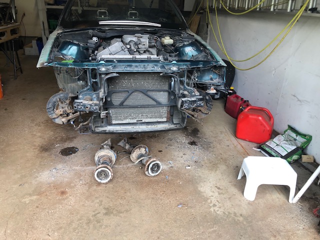
Things can only progress so far without the mechanical bits that are needed for the car. I’m talking about things like the engine, transmission, differential, CV shafts, spindles, brakes etc. Things that we can’t make and currently have none of. The Locost is a small, front engine, rear wheel drive car, a configuration that has become almost extinct as manufacturers bought into the front wheel drive craze of the 80’s.
One of the cars that still fits the bill is the Mazda MX5 Miata. These are very popular Locost donor candidates but finding one in Southern Ontario that is suitable for parting out (ie in bad shape) at a reasonable price is all but impossible. The other option is to piece together the parts from multiple donor vehicles. That’s the route we will be taking.
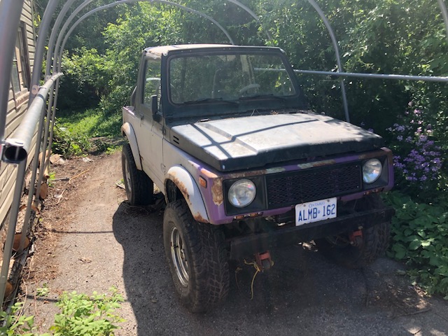
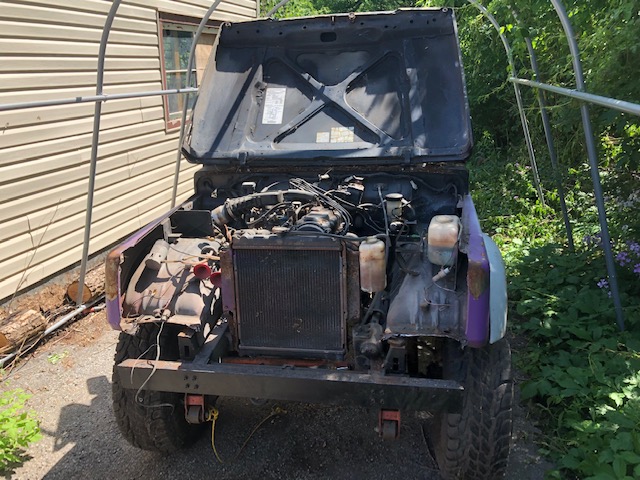
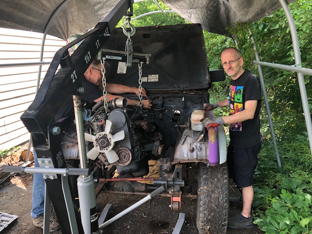
So, I am off to Barrie, Ontario to meet with Paul. He has a 1992 Suzuki Samurai that is destined for the recycle yard. Before it goes we will be harvesting some parts and sending it on its’ way a little lighter!
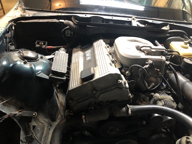
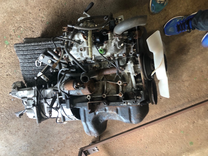
The big things coming out of it are the engine and transmission. It has an aluminum 1,300 cc SOHC inline four mated to a 5 speed manual transmission. In stock trim it puts out 68 horsepower – in non stock trim we will have to see. The engine and transmission combined weigh about 175 lbs., that will help to keep the Locost as light as possible. Unfortunately, none of the Samurai suspension or steering components will be useful, we will have to scrounge them from other vehicles.
Today’s visit is to do the pre-work for the engine and transmission removal that will take place when Tom comes for a visit from Belle River in the next couple weeks.
We are ready to operate.
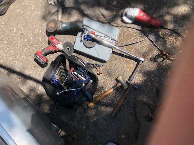
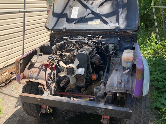
The Samurai and a selection of precision tools that we will be using. Angle grinders and cutting wheels figure predominantly in today’s operation. We will be removing anything on the front end that is going to be in the way when we go to pull the engine.
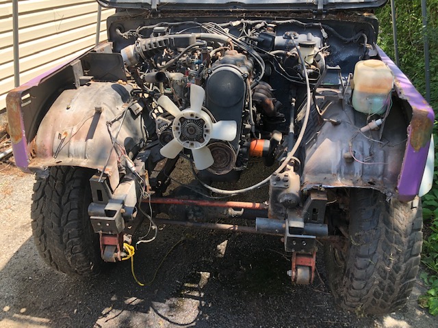
Removing the radiator, front bumper and any associated sheet metal leaves the engine and transmission ready to go.
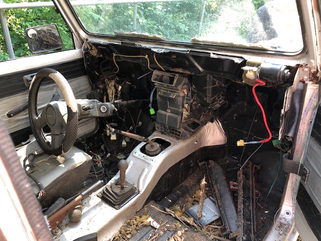
We will also be taking the steering column, instruments, headlights, turn signals, wiring harness, electronic control unit, ashtray, lighter, paint and anything else that may be useful!
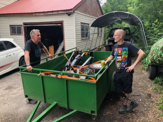
Tom has joined us to pull engine and transmission out. Everything goes very smoothly and “Yoshi” is loaded and ready to head back to Mississauga.
Back home with a side trip to the car wash to clean some crud off the engine and transmission. Here it is resting comfortably, it tucks under the build table quite nicely.
This post covers work done over a span of two weeks in May.
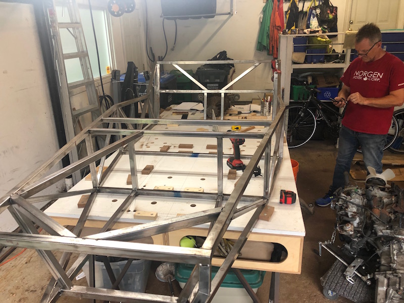
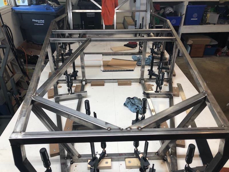
With the trials of the front frame in the past it’s time to put on some uprights and top rails.
This is one of the uprights located at the fire wall. It is positioned with a couple of welding magnets. A small framing square is used to ensure it is stays perpendicular to the build table while I tack it in place. We are tacking as we go now.
Moving towards the back of the car. The second pair of uprights are positioned and tacked in place.
Now the top rails that run continuously from the front frame to the back upright can be put in position and checked.
Welding magnets are super handy, here they are keeping the rail aligned with the top of the front frame and the side of the first upright. The length and vertical alignment are perfect, just meeting the edge of the second upright.
The horizontal alignment is not perfect, but it is close. That is corrected with a small adjustment to the uprights (nudge).
Taking diagonal measurements from the corner of the front frame to the back corner of the second upright to check that things are square.
Top rails tacked and the cross rail and center uprights at the fire wall are fit and tacked in.
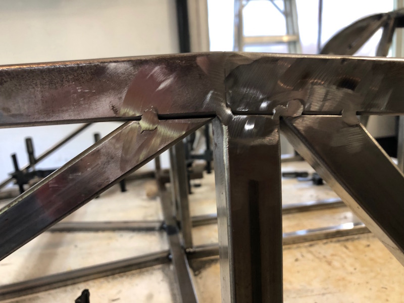
Now two uprights just behind the front frame are cut and tacked in. They overhang the outside of the top tube slightly where they meet. The top tube is not parallel to the center line of the car and the upright is perpendicular to it. This creates a small overlap at the front of the upright. This is the way it is supposed to line up. These are critical frame tubes as one of the front suspension mounting brackets attaches to each.
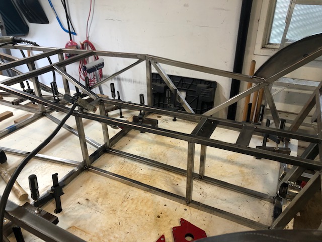
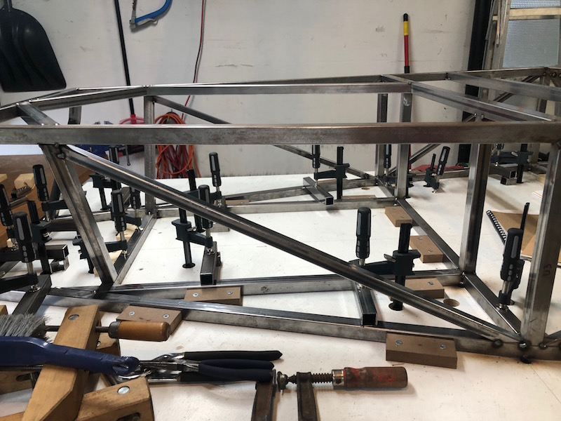
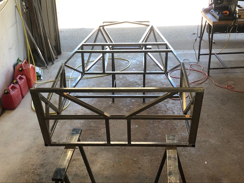
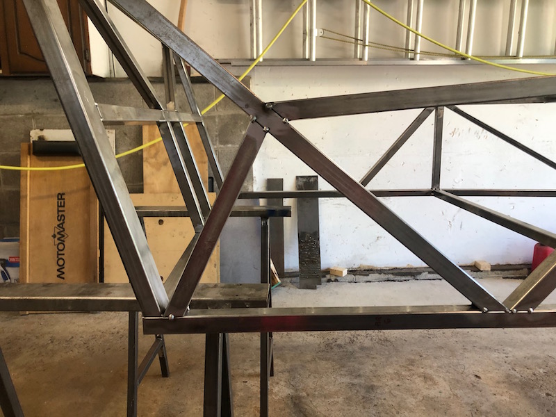
Moving to the back of the frame, it’s time to attach the sloping back rails that are made of 1×2″ tubing.
Using a bunch of Harbor Freight clamps allows the angle to be adjusted incrementally to get the correct position. A plumb bob is used to check the distance before tacking.
One side tacked, rinse and repeat.
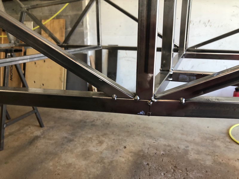
Next two diagonal supports for the sloping back rails are cut and tacked in along with the horizontal top tube.
The top rails have been connected from the second upright to the diagonal back rail support. Things are going fast, I wish I took a better selection of pictures!
The cross rail and two uprights that form the back of the transmission tunnel are put in next. It is good to have lots of welding magnets.
The diagonals that go from the cross rail to the top rail are clamped in position for tacking.
Back to the front end to install the two braces from the center of the front frame to the top rail at the first upright.
The long diagonal running back to the cross tube at the firewall is added next. It is positioned for a right hand drive car and will eventually get flipped to the other side when I figure it out.
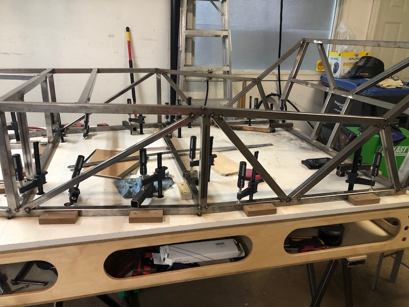
Diagonal bracing cut and tacked in the side frames, 1″ tubing in the back section and 3/4″ in front of that.
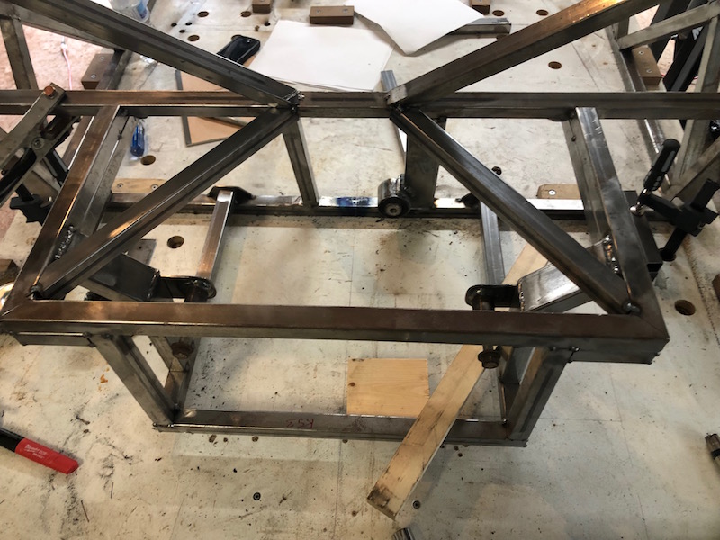
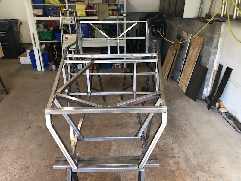
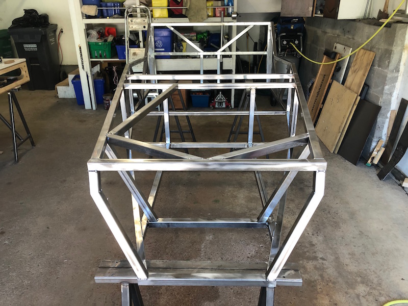
At this point the front of the frame is pretty complete. It is well triangulated and everything is tacked solidly. Currently the frame ends at the back of the passenger compartment. Next time we visit it we will be building out the back end that carries the differential, rear suspension, fuel tank etc.. In order to do that we will need to shift the frame forward on the bench a couple feet to get the back end on the build table. This is a perfect chance to get the frame off the bench and have a weigh in!
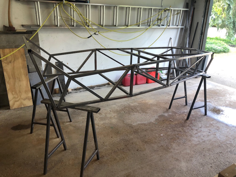
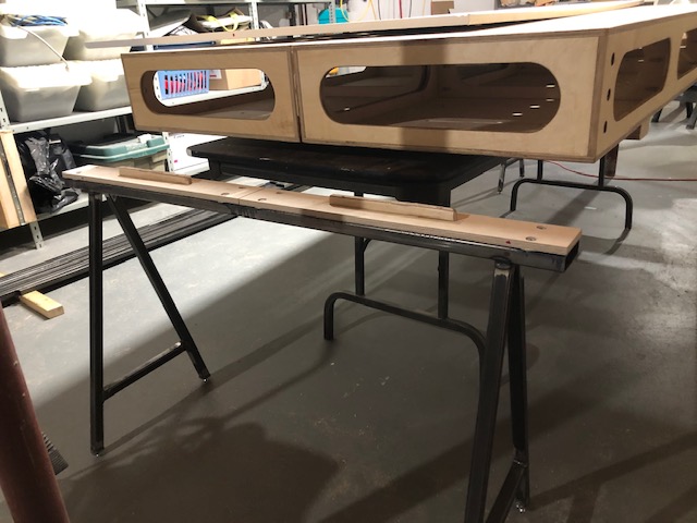
Here it is on a few of those kick-but two foot sawhorses from post 11. At this point it weighs about 80 lbs, if a bathroom scale is to be believed.
That’s about all for this post, here are a few pictures.
This post covers a time period of about two weeks from late April to mid May.
Very early in the build you are tasked with building the front frame for the Locost. By this time I have cut all the lower frame tubes and made some angle cuts successfully. I am feeling pretty good about my fabricating skills, however…
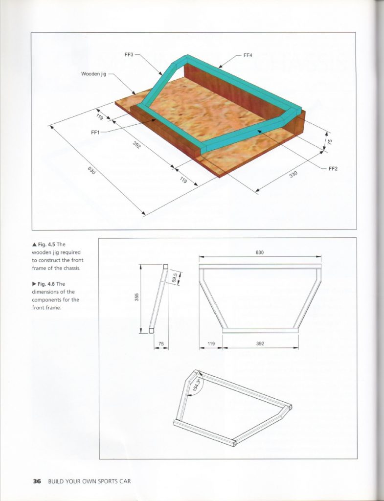
…this piece requires compound angles to be cut and a jig to be made to facilitate assembly. I really struggled to get this right, I made it twice before moving on.
What they don’t stress in the book is the importance of front frame. Four of the front suspension brackets will get welded onto it. If it is not perfect there will be problems getting the brackets aligned. Fortunately, nothing is fully welded by the time you get to that point so things can (and will) be adjusted.
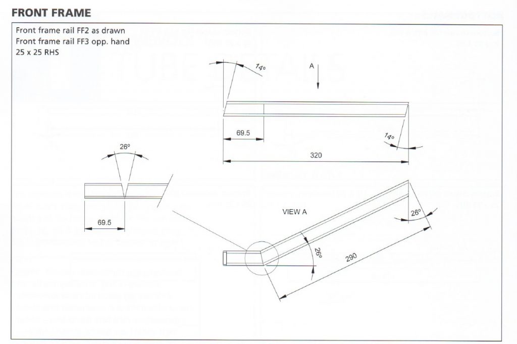
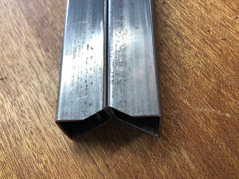
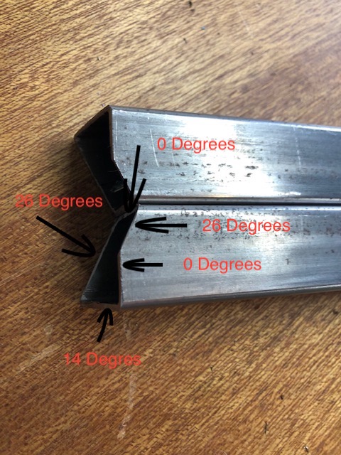
This is the detail drawing that you work from. Where the drawing says take a 26 degree wedge out of the tube I opted to cut the tube off at 13 degrees on each side and tack it back together to from the angle.
Cutting compound angles: After the first angle is cut, rotate the tubes 90 degrees. In this case one is rotated left one right as they are a handed pair. The second cut trims the tube end at the second angle leaving the tubes with two faces that need to be cut/ground/filed to match the angles of the opposite sides. EasyPeezy…
This was my first attempt at making the jig on an old piece of MDF.
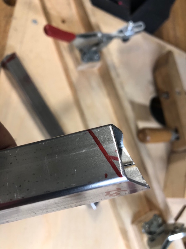
Cutting, clamping and tacking the tubes together. At this point I realized that it would be far easier if the two angled arms were tacked together before fitting. I won’t make that mistake again, there are plenty of other mistakes to be made.
I persisted, for better or worse, got things lined up and tacked the frame together.
I put the frame in position on the bench but the top tube isn’t level. I checked my jig and it was definitely not flat contributing to the issue – live and learn.
I rebuilt the jig using the top of the assembly table as the base, I know that’s flat. I also tacked the dog legs before fitting them on the jig. This gave a satisfactory result.
The top tube is now level and things look good. The frame gets height! Time to tack everything together.
Typical joints on the frame. Every tube is clamped to the table in two locations and all the joints are nice and tight. I drilled relief holes in the MDF top at all the joints so I could tack close to the bench top without causing a fire. My tacking is way better than my welding!
Well the day has finally arrived to move all the stuff that I have been making into the garage and start building the car! I warned you up front that it would take a while to get to this point.
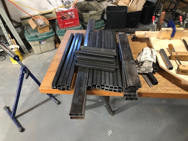
Picking up the steel to start the build.
Moving everything to the garage, my son Erik lending a hand.
The first time the bench has seen the light of day. Making adjustments to level the bench and ensure that the top is flat.
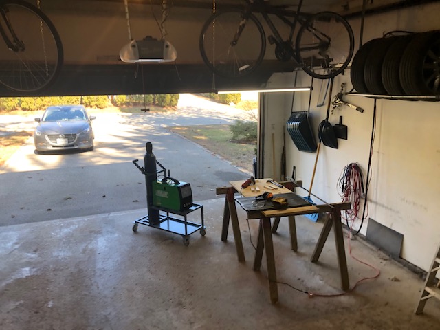
Top on the bench and the cutting table stowed in parked position. In this configuration I can still fit one car in the garage overnight. I pull the cutting table into the open side of the garage if I am going to work on the Locost. I am working half time so my time in the shop is not unlimited.
This is the start of the build with the first frame tubes being cut and clamped on the bench. All of the work over the winter making stuff is really paying off. The cut tubes are accurate in length and angle. They are lining up perfectly on the bench. Happy days!
The first tubes being cut and positioned on the table. Includes my daughter Emily, the videographer, buzzing around.
The end of day 1 and all of the base tubes are cut, clamped, and waiting to be tacked. There is a long period of time building the frame where it is only tack welded. In fact, the frame is pretty much complete before you fully weld it.
This has been a very productive day. At this rate the car should be done in a couple weeks! LOL
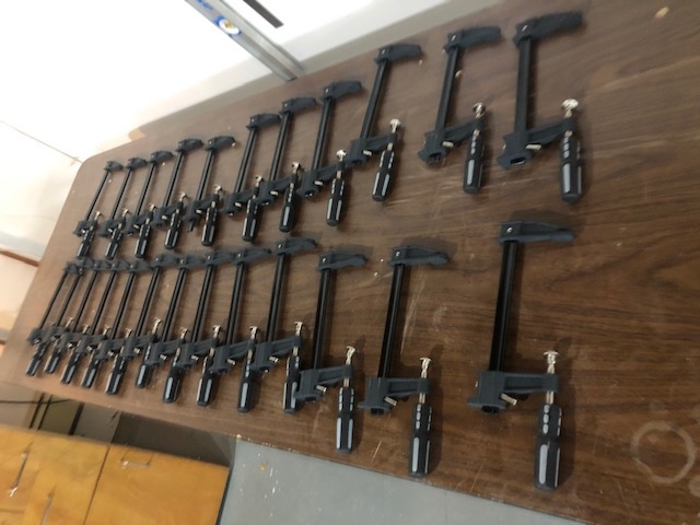
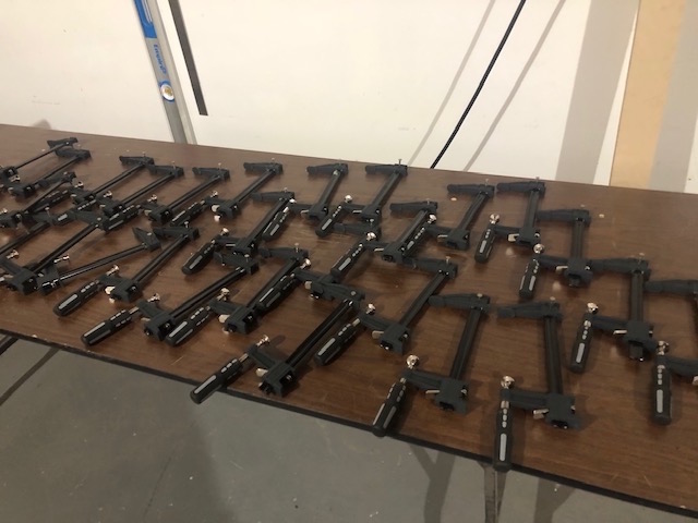
Just in a nick of time my brother Tom delivered a load of clamps that he picked up at Harbour Freight somewhere in the US. The 30 clamps weigh at least 50 lbs. and he humped them a few kilometers from the store to the truck stop where he was parked. Many thanks!
All lined up and ready for “processing”. Any time that you need to do the same series of operations 30 times it gets a “little” tedious, but here we go.
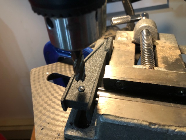
Using a fly cutter in the drill press to clean off the rivet heads, this is a lot easier than a pointy drill bit – thanks for that tip Tom! Followed by a quick pounding on the vice anvil with a hammer and punch to remove it.
The clamp heads are pressed on before they are riveted. I needed to press them off or pound the bjeezus out of each one with a hammer and punch. I tried method two on a couple but it was just too inefficient, maybe I didn’t have a big enough hammer? I didn’t have a press, but I did have a bottle jack, so I decided to make one. I also made a small tool that fit the shape of the bar and used that on the jack to press the heads off.
That was fun, seems my organizational skills have gone out the window as everything just gets thrown in a pile now.
Every clamp needs to have the end of the bar cleaned up with the angle grinder and flapper disk so that the heads can slide on and off easily.
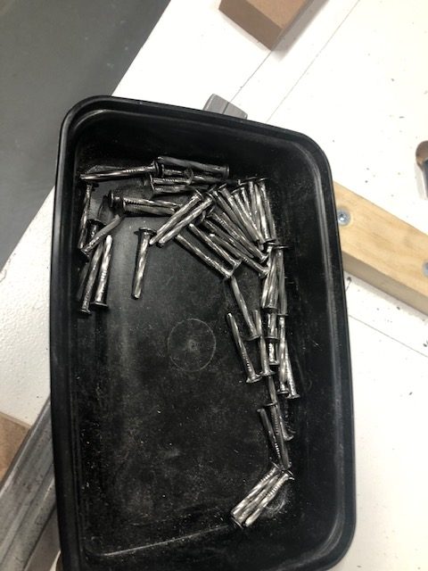
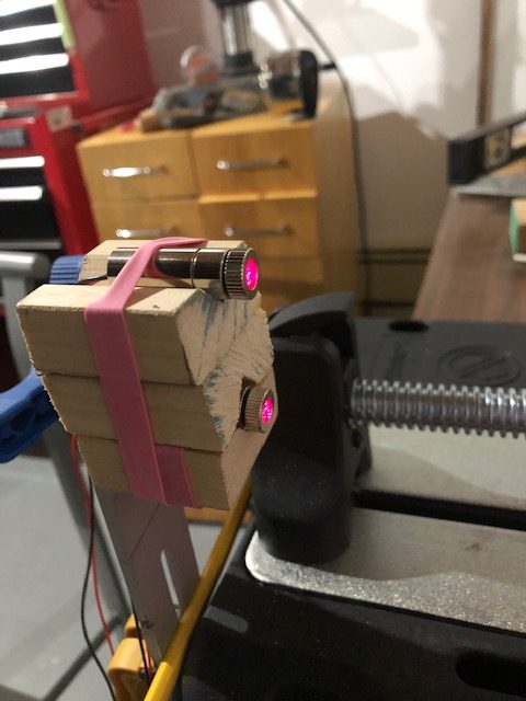
Finally! We need to make new pins for all the clamps. Nails trimmed with the angle grinder will do. The End!
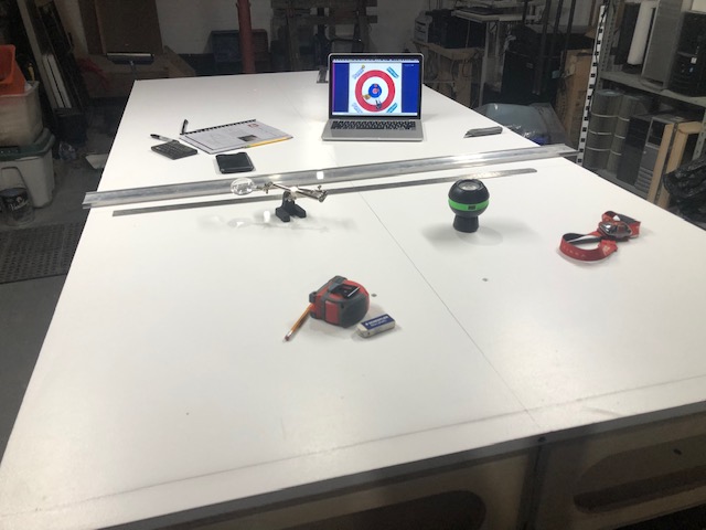
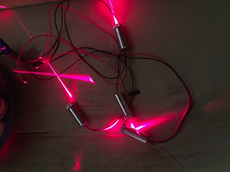
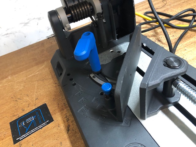
Now that the cutting table is complete it’s time to attach that laser guidance system. I decided to attach it to the side rail of the table frame rather than directly to the saw.
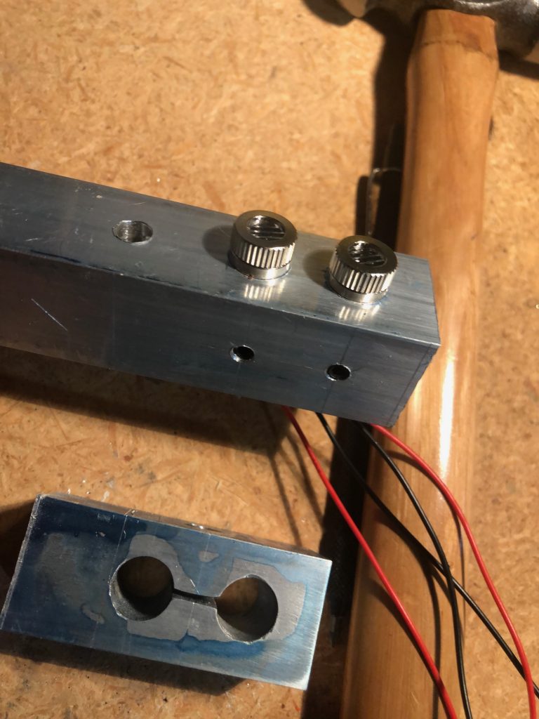
Here are the basic components of the mount cut and ready to assemble. The U bracket was made from a piece of square aluminum tubing. It will enable the laser head to pivot to create that blade width gap between the two lasers.
The steel plate with the slots will allow the bracket to be shifted left/right to align with the saw blade. It took a long time to drill and file those slots – steel is hard to shape.
The bits have been to the garage and back, they are tacked together and ready to test mount. The square tube will bolt onto the side frame and the flat slotted plate will bolt onto it.
The two Allen screws on the base allow the mount to slide in the slots. The U bracket allows the head to pivot and it can swivel to help line things up. Time to weld this thing.
Trying to start a fire.
Everything looks better after you massage it with the angle grinder.
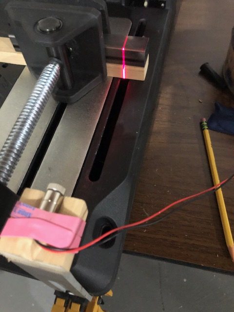
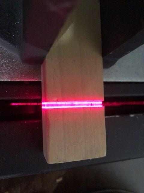
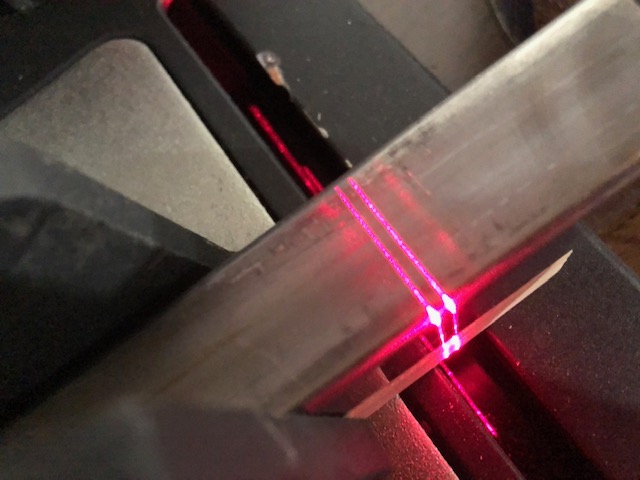
In order to align the lasers I made a guide out of 1/8″ plate. It was cut on the saw and can be position by lowering the stationary blade through it. I used with a sheet of white paper under it to make the lasers more visible. It took a bit of time but I was able to get things aligned nicely. I was worried that any bump of the laser head would knock it out of alignment. Once it was bolted down it was solid and the alignment wasn’t disturbed by any “normal” contact.
The chop saw found a permanent home on the old door, but that home needs a base under it. The cutting table is fairly big and I was planning to build the base using a couple rectangular frames, one for each side. Sorry I lost the “detailed” plan for this one. I was concerned that the rectangles be square as well as flat after my welding cart experience. I came across a website with a guy making trailer frames who had some good advice using a practical application of math of all things!
The theoretical: two intersecting lines form a plane which is by definition flat.
The Practical: take two pieces of straight steel and clamp them together forming a “V”. Now the two arms define a plane and any straight material that sits across them will be on that same plane. So, here we go.
The basic setup. The two 10′ long tubes laying on the new sawhorses are clamped together with a pair of steel plates. This should form a plane. The 2 pieces of tubing with the welding magnet keeping them square are each resting across both arms and therefore should be flat when they get tacked together.
We can use the same principal to add the other sides of the rectangles and they should be pretty flat.
Here are the 2 finished sides. The bench will sit solidly on four steel feet but will have a pair of castors at one end so that the opposite end can be lifted to move it like a wheel barrow.
The finished frame with castors mounted and tabs welded on the top to attach the cutting table (the door) on. More practice with the “hot glue gun”!
The frame was made narrower than the door so that it could be moved more easily on the torturous route between the basement and garage. It too will be facing an annual migration.
In order to hold up the work bench I need some sturdy saw horses. The bench plans call for folding saw horses made of plywood but I will be making mine out of steel. Let the cutting and welding begin!
Cutting Sawhorse legs from 1″ square 16 ga. steel, two at a time.
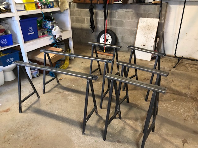
A simple jig to make welding up the legs easier. I will be making two 4′ long sawhorses and four 2′ long ones. That way I can use the work bench as a 4’x8′ surface or two 2’x8′ surfaces.
Making leveling feet for the 4′ sawhorses.
All the parts cut and ready to go to the garage for welding.
It’s a beautiful day in March! The shop looks a little empty though.
All the legs welded and ready to go.
The tops of the saw horses are 1×3 16 ga. steel. Welding magnets hold the legs square on the tops.
typical (I wish) weld, leveling foot on, mans best friend!
All present and accounted for.
Meanwhile back in the shop… the 4′ saw horses get fancy top plates with tabs on top that fit into a slot in the bottom of the bench top to keep everything located.
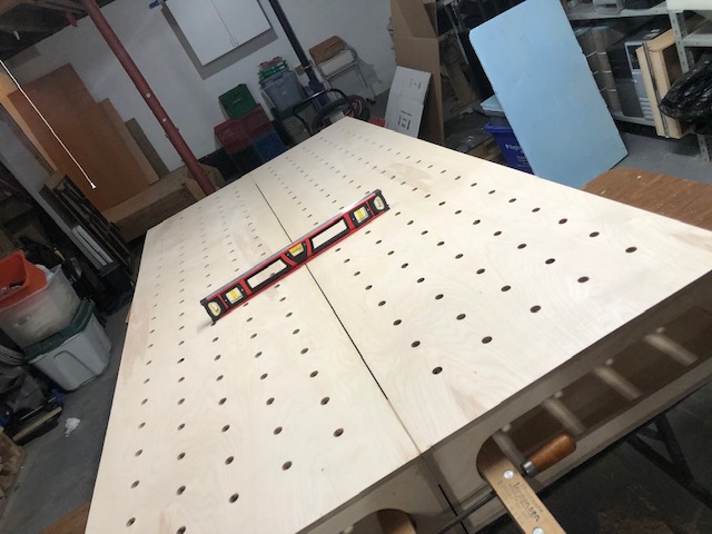
The top plates are split in the center and shimmed independently to ensure I can get the two sides of the bench as flat as possible.
Using the flat bottom edge of the levels to check that the top lies flat. All that fuss’n pays off.
I was really happy with the way the bench turned out. The last thing I wanted to do was mess it up by welding a bunch of steel on it, that was never in the cards. I bought a 3/4 inch thick sheet of sacrificial MDF to lay over the table and painted it white with leftover ceiling paint.
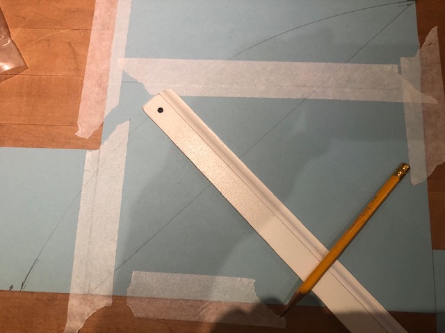
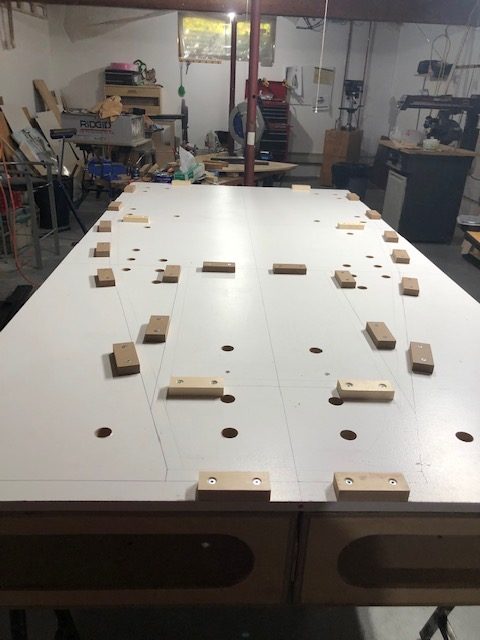
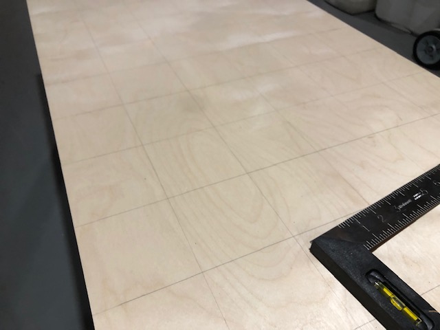
The next job was to mark lines for the lower frame tubes. A fine tipped marker and a good long steel ruler make the job go easier. Adding a centerline comes in handy for checking a lot of dimensions. You can enjoy watching curling while you work, it is February in Canada after all.
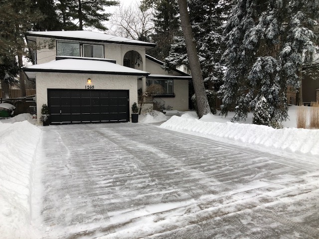
Occasionally I need to take a break and shovel the driveway.
I was planning on using the holes in the bench top to clamp all of the lower frame tubes in position. In order to do that I needed to make holes in the correct location in the MDF sheet. I used my Dremel tool with the 90 degree head and a small drill bit. I made a 3/4″ diameter guide with a hole for the drill to pass through. Now I could drill through from the inside of the table. I put the guide in the hole in the bench top and drilled up through the MDF. Now I had a well centered pilot hole in the MDF.
Now I drilled a 1.25″ hole with a Forstner bit using the pilot hole as a guide.
All lines laid out and clamping holes drilled.
I will be using 6″ bar clamps to hold down all the lower frame tubes. The rivet that holds the head of the clamp on will need to be drilled out and the head pressed off. The bar is ground down a bit so the head can slip on and off easily. Now the bar can be put through the hole and the head slipped on inside the work bench, a pin is slipped through the head and bar and the clamp can be tightened. This sounds a bit cumbersome but I quickly got pretty fast at it.
The 4″ hole spacing on the bench does not line up in the perfect position for all of the frame tubes to get clamped directly. Some of the tubes will get clamped indirectly.
Wooden blocks were added to the MDF top to make alignment of the frame tubes easy and accurate.
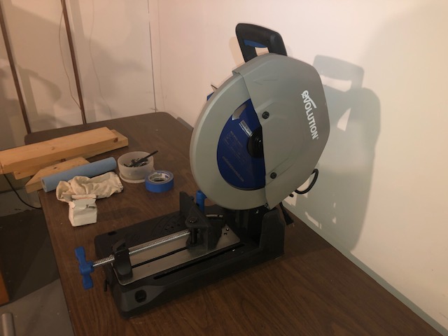
I’ve been concerned about accurately cutting angles in steel tubing using the chop saw for some time. Although the new saw is much improved over the original it still has a small miter gauge/scale which will make it very difficult to accurately set random angles. There are a large number of non standard angles in the plans (say 9 degrees) that need to be set accurately. I have been thinking about building a cutting table with a large fence that would replace the clamp and miter on the saw, it could make setting fiddly angles easier. Nothing ventured…
The first order of business was to take the clamp and associated hardware off the chop saw and put it into storage. Then the naked saw was bolted down securely onto a good work surface, one of the much abused folding tables.
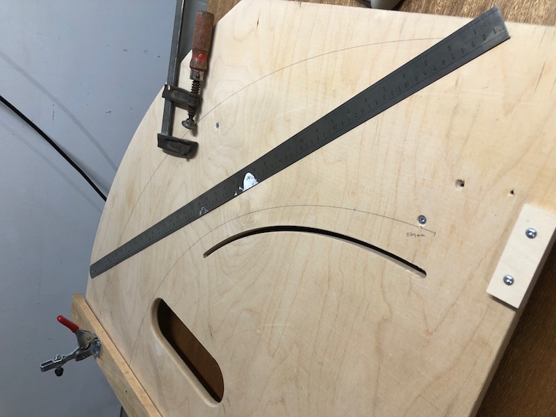
Next an old board that I had made years ago to use with the router for flush trimming was repurposed. It was shimmed level with the bed of the saw and attached to the table. The trimming board has a pivoting fence on it and the idea is that it can be used to set any angle like a giant protractor.
Using some sketchy clamping work to do a test cut of the most acute angle required in the build. The steel was clamped to the fence and and the tail end of the fence is clamped to the board at the appropriate angle.
Success! The test cuts look very good. The setup gets upgraded to an old solid core door as the work surface.
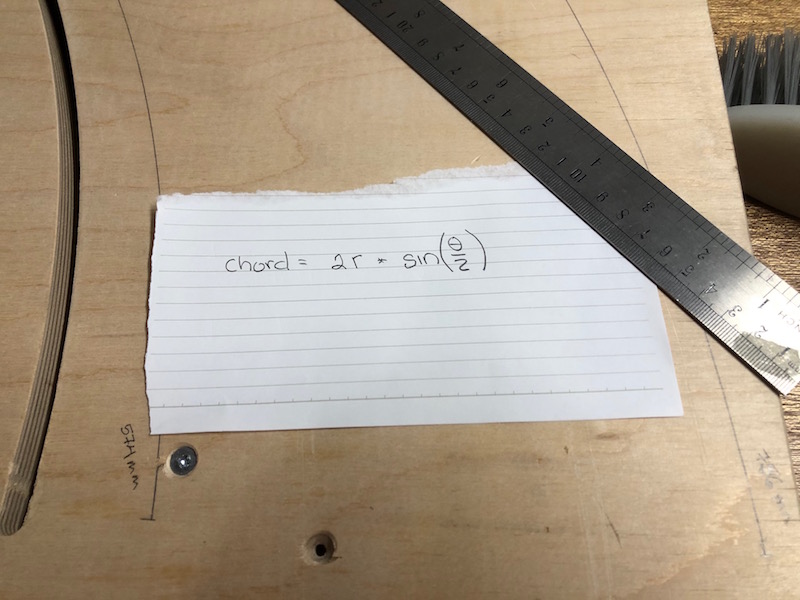
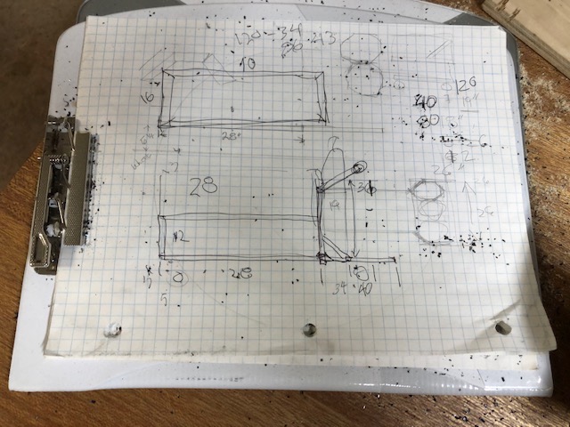
Now we can use math to set the fence angle for any cuts required. The fence traces an arc of radius 756 mm as marked on the board. That is the radius used to calculate the chord of any angle using the formula on the paper in the left image. At that radius a change of one degree results in a change in chord length of over a centimeter. That means that small differences in angles are easily discernible. We will be able to set angles accurately and differentiate between 8 and 12 degrees for example. I used a one meter steel ruler to measure and mark the distance from the stop position of the fence (90 degree cut) and any angle desired. An Excel sheet was created to calculate the chord of every angle. A digital angle measuring instrument comes in very handy as well.
The fence gets upgraded so that it is 2″ high. It can now support two 1″ tubes for cutting at the same time. This keeps matching parts consistent and cuts the work in half.
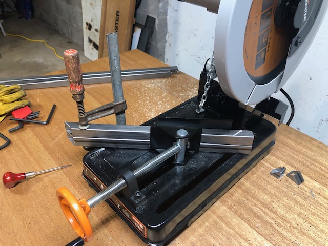
Here is the setup ready to go. The red handled toggle clamps are really only useful to hold the work in position for clamping. I normally use two of the large hand screw clamps to securely clamp the steel to the fence. The fence is then clamped to the board with a single bar clamp at the free end.
The saw is powerful. Trimming a short piece off the end of the clamped tube can result in it getting launched with considerable force against the wall or into the saw guard. Yikes! For this reason it is not recommended to cut short bits on the saw. Unfortunately, there is no way around it so I have taken to holding the bit being cut off with a pair of long handled water pump pliers. This works really well, especially with the laser system to show where the blade is going to cut.
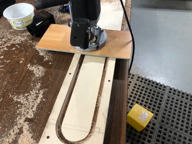
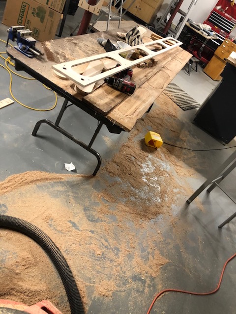
Another shop reconfiguration to set up the router again. This time to round over all of the inside edges that were cut using the router/templates.
Followed by a pass with the random orbital sander. A repurposed hanging air filter complete with custom cardboard hood helps keep the dust under control.
One half of the bench ready to assemble.
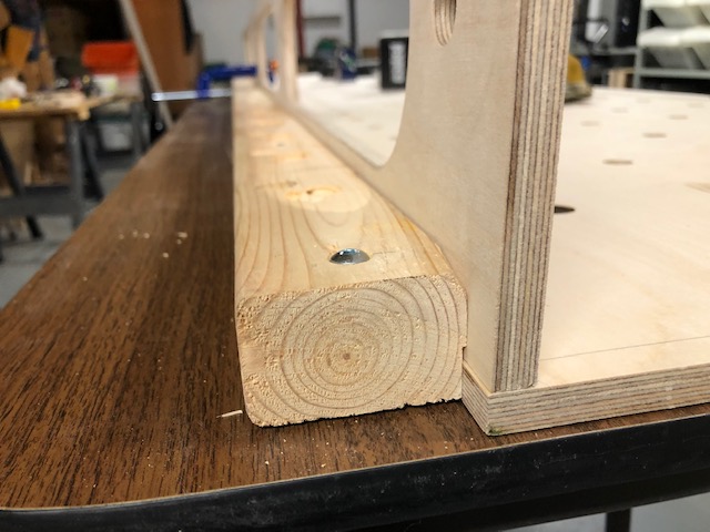
I used this guide (screwed to the assembly table) to ensure that the bench top would be slightly proud of the side stringer. It would be cleaned off later with a flush trimming bit.
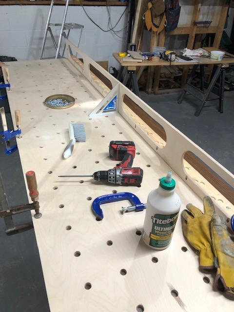
The first side attached, things move pretty fast at this point.
The side and cross stringers glued and screwed onto the top. You can see the pocket screws in this view.
On to box two.
Resting for the night. Bottoms will be attached after the glue has dried.
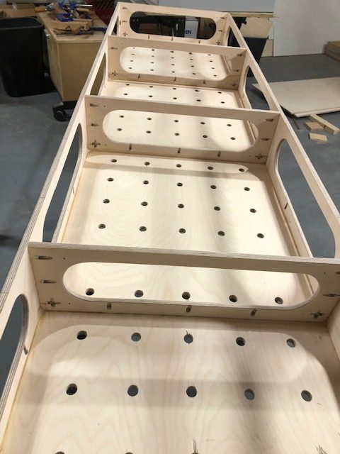
The next day it’s time to put the bottoms on. At this point the boxes feel a little “flexible”, they can be twisted a bit if you force them. Gluing and screwing the bottoms on fixes that!
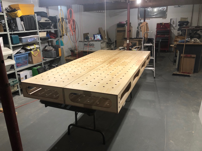
All the glue has set, the boxes are very rigid. Using 1/2″ material means that the bench is reasonably light. I can muscle each half around the shop by myself and I’m old. Moving them to the garage with help will be no problem.
One last trip to the sanding table.
A couple coats of urethane applied, now just a proper base is needed.
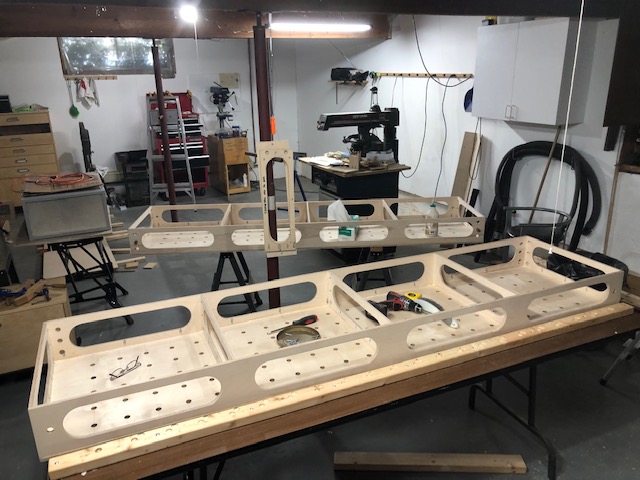
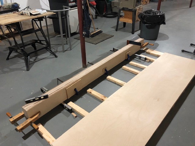
In order to build a Locost you need a 4’x8′ table to assemble and weld the frame on. The table needs to be flat so that your frame will be true. It’s also a good idea to make the bench sturdy as well. The frame will weigh about 140 lbs by the time its’ ready to come off the table and in addition it also needed to support my mass as I spent a lot of time on the table welding and grinding towards the end of the frame build. It was important that the bench be moveable as I was going to build it in the basement and needed to relocate it to the garage in the spring. I also wanted something that would replace the folding tables that currently serve as my work benches once the frame was completed.
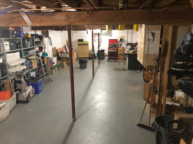
This is my basement after the purge. It took me about a month to get it to this state so I would actually have room to build something! No before pictures – too embarrassing.
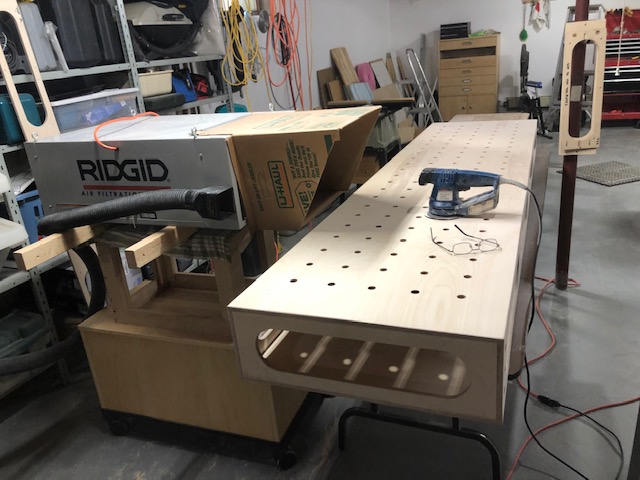
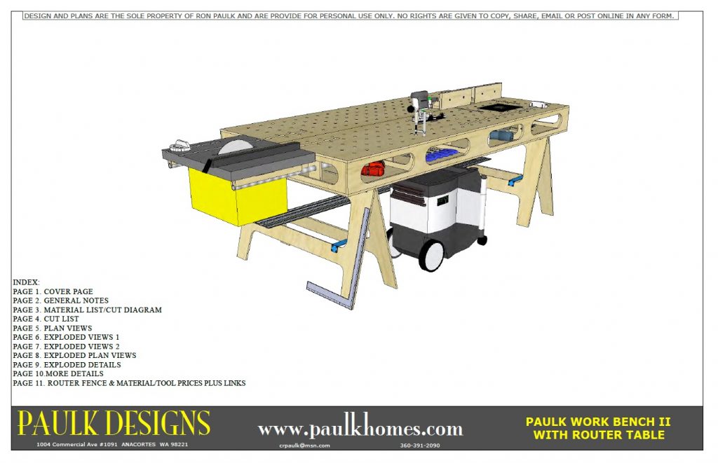
In searching for bench ideas I came across the Paulk Designs website. Ron Paulk is a craftsman who designs sturdy, light, transportable wood working benches and systems and sells plans for online.
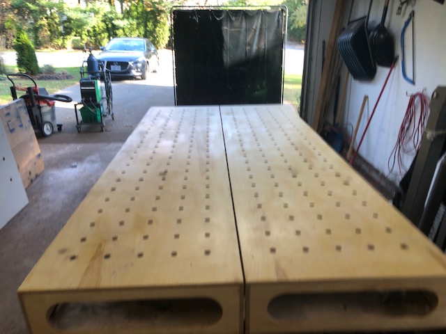
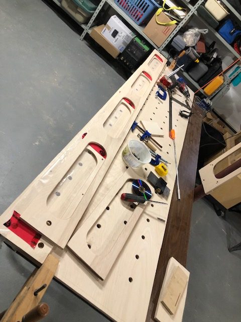
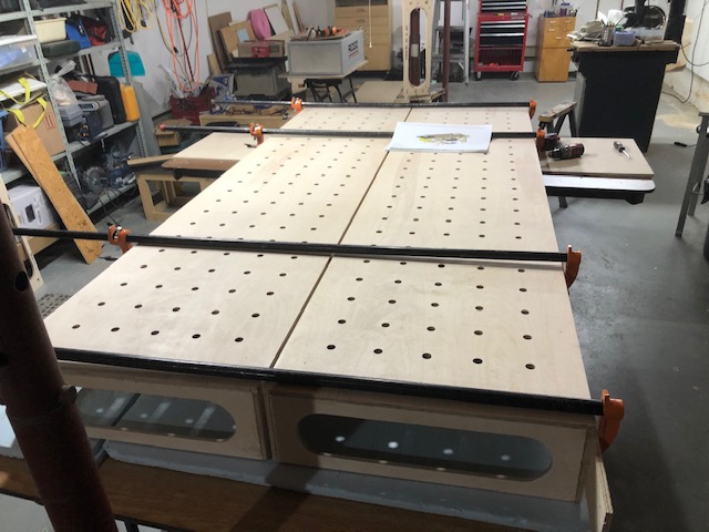
This 4’x8′ bench is made up of two 2’x8′ torsion boxes fabricated from 1/2″ plywood. The top of the bench has 3/4 inch holes on 4 inch centers for clamping material. Without the add-ons for the table saw and router this would make an excellent bench for the build.
I have to say that this is one of the most ambitious wood working project that I have ever taken on. I am not a great wood worker so Ron Paulk’s series of videos showing the details of the construction were invaluable. At the end of the build he hopped on to the bench and started jumping up and down! I think it will be sturdy enough. Building the bench took almost a month of my free time but it gets covered in a couple posts.
I picked up the material to build the bench. I used 1/2 inch (technically 12mm) Baltic Birch plywood and had it ripped to width for the tops and stringers at the wood supplier since I don’t have a big table saw or track saw to rip 4’x8′ sheets accurately and easily.
I marked out one of the tops with a 4″ grid for the 3/4″ holes. A plunge router will be used to drill the the holes.
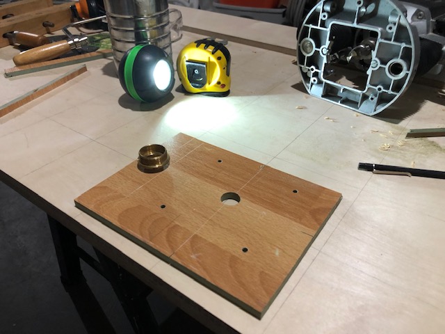
In order to make the hole drilling easier I made an indexing guide out of a scrap piece of laminate flooring and a brass template routing guide that happened to have a 3/4″ OD. The guide screws onto the bottom of the router in place of the standard bottom plate.
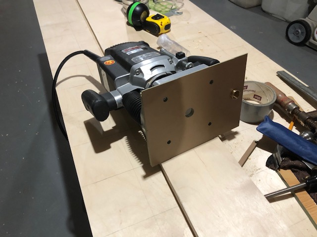
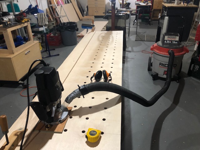
The plate is attached and you can see that brass guide extending through it. After the first hole is drilled the router can be moved along a straight edge and the trailing 3/4″ guide will drop in the hole and position the router for the next hole.
Here it is in action. The router is moved along the straight edge and the indexing guide positions it. The shop vac is connected to the router to clean up all of the sawdust before it hits the floor (and there is a lot of it!). Plunging through both tops together cuts the work in half!
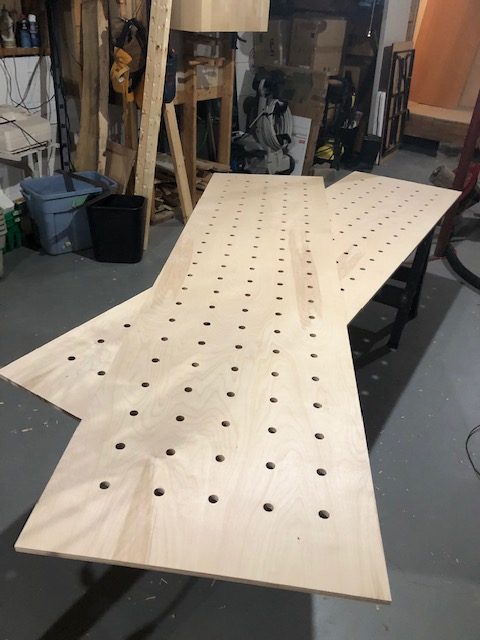
All done, except for everything else!
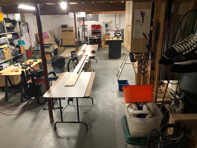
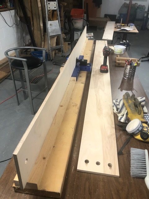
The shop reconfigured with the router table set up between two 8′ folding tables to use as a jointer. I am taking a small cut off each side of the stringers to clean up the saw cuts and make the widths consistent. With 8′ material you need 16′ feet of space to do anything!
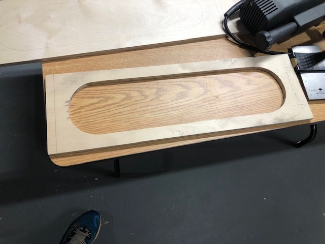
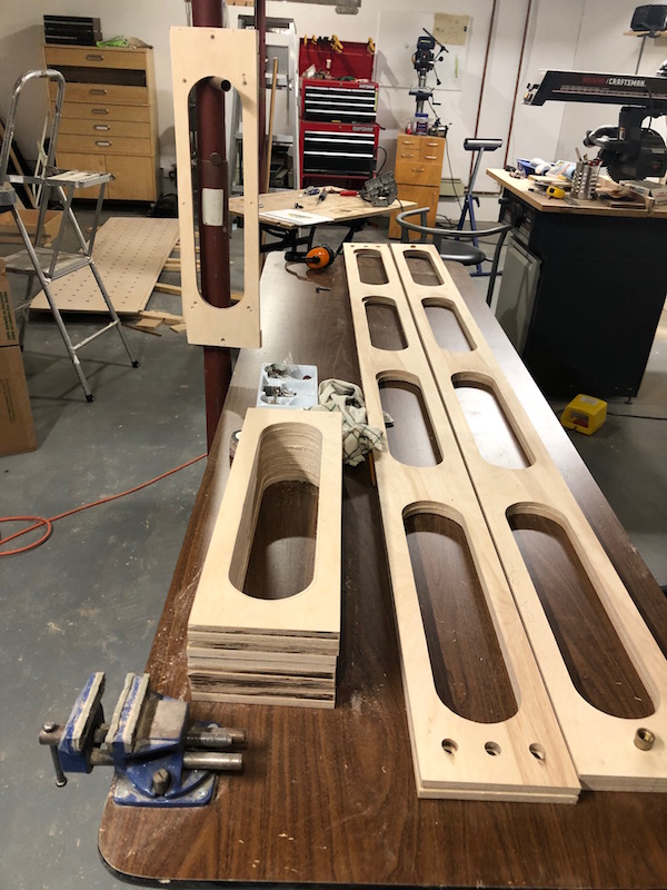
The side and end stringers are cut using the router, templates and a template guide. I first made a master template by hand, it would be used to cut the openings in all the templates. The master is made oversized to compensate for the size reduction that happens when cutting with a template guide.
Another base was made out of scrap laminate flooring. It’s wide enough to bridge the templates and make cutting steadier.
Making the templates, the master guide is attached to a clean piece of plywood and the router cuts the shape. I was using a 1/2″ spiral bit for the cutting. A couple laps around the guide and we are done.
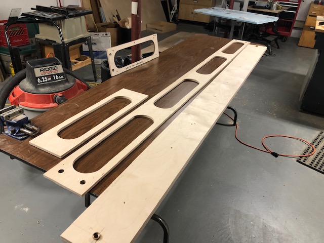
The finished templates ready to start cutting the side and cross stringers. The hand made master template is leaning against the post.
Another shop reconfiguration. The torsion boxes are held together with glue but they also use pocket screws (and quite a few of them) to keep everything secure while the glue sets. The blue box is a guide for drilling holes for the pocket screws. All of the holes were were drilled before cutting the templates with the router.
On to cutting, the 1/2″ bit generates a lot of sawdust! An old cedar board is placed under the template being cut so that the bench top does not get chewed up.
All the stringers cut and ready for the next step .
Ok, that title may be a bit misleading. We are not actually cutting the steel with the lasers. We are going to use the lasers to show where the chop saw will cut the steel! I saw a post on the web of a fellow that attached a low cost laser to his cold cut saw to aid in lining up cuts. What a great idea! Since winter was coming and I would be in the basement unable to weld for a while I thought why not add that to the list of things to make as it will definitely help in building things.
These are low cost line lasers that you can order from Amazon.ca for about $5 each. A Fresnel lens is mounted in front of the laser to focus and generate a straight line rather than a point. They are a little finicky to adjust and lock in but you can make them work.
The concept will be to mount two of the lasers on some type of bracket attached to the saw base or the cutting bench. The lasers will be offset (left/right) in order to mark both sides of the saw kerf as the blade is a few mm thick. For this “proof of concept” experiment I am using some wooden blocks, rubber bands and an old Ikea curtain bracket.
The final test setup with both lasers in position.
A piece of wood was clamped in the chop saw and cut part way through to act as an alignment guide. The lasers were aligned to the each side of the cut.
In operation the lasers should paint lines where the the saw blade will hit the steel making it easier to measure and cut. This looks very promising, it’s time to build something a little more industrial.
I had a piece of 1 inch square aluminum bar so I started drilling it to make the laser holder. These are the ill fated Mark I and Mark II prototypes, both discarded due to design flaws.
Third times a charm. This is the start of the third iteration of the holder. The two large holes (slightly stepped) are for the lasers to slide in, the single smaller hole below them is for a pivot and four tiny holes will be drilled and tapped for set screws to lock the lasers in position.
Here is the rough holder with the lasers installed for testing.
Finishing the laser head
cut the top corners off
round the top
cut the holder off the bar
cut the bottom corners
round the bottom
sand with wet paper
The finished holder with lasers installed and ready to go. The only power tool used was the drill press, all cutting and finishing was done by hand. Aluminum is a lot easier to shape than steel!
On the test bench. The head is tilted to offset the lasers (left/right) so that they mark both sides of the cut. At this point I don’t have a proper mount to attach the laser head to, that will have come in a future post when I figure out what to attach it to!
Nothing like using a tool to see if it is suitable for the job.
The Rage 2 has some significant short comings. Adjustment of the miter is cumbersome, an Allen screw needs to be loosened, the miter set manually using the scale (no presets) and then locked down.
There is no quick release on the clamp, it must be wound out by hand in order to change the size of material clamped or change miter setting. I was using a small framing square to set 45 degree miters accurately, this required the clamp to be wound out all the way in order to get the square in position.
The base of the unit is pretty light sheet metal, it could be much sturdier. All things considered I decided an upgrade was called for.
Enter the replacement…
The Evolution S380 CPS. A major upgrade that is well worth the difference in price.
It has cast metal base, miter with lock down for several different angles and a quick release clamp. A much sturdier design overall.
It comes with a 14 inch steel cutting blade but can accept a 15 inch blade.
Ok, so a welding cart is not really a vehicle but it does have a frame and wheels so it is a step in the Locost direction.
It’s good to start with a plan. In this case I have gone with PAD (Pencil Aided Design) for the welding cart rather than CAD. I will have to go digital sooner or later…
Cutting components for the frame with the chop saw (two at a time) to ensure matching pieces are identical. I am using 1″ square 16 ga. tubing – the same material used in the Locost frame.
Bottom frame welded together. Keeping things flat is more difficult then getting them square. A steel welding table to clamp the tubes on would be a great help.
Starting to look like the plan!
Progress.
The Good, The Bad and the Lumpy.
Something to attach the wheels to.
Stitching the bottom shelf to the frame.
Checking the fit.
Wheel detail – nice weld!
Capping off all the open tubes, a lot of angle grinder work required.
The tank holder slips over the two horns to secure the tank.
Into the basement paint shop for primer and paint. This was a bit of a disaster as Tremco rust paint is oil based and really smells up the house. Battle ship grey was applied in the garage despite the cool weather.
Before you can join metal in a useful way you have to cut it into appropriate pieces. I started using a wood cutting chop saw with an abrasive blade installed. Although it works, this method is a slow and noisy plus it produces a lot of sparks, smoke and heat – things I would rather avoid.
The alternatives were to acquire a steel cutting band saw or a cold cut chop saw. Band saws are quiet and a bit slow, chop saws are noisy and fast. I looked at both and opted for the chop saw. This is a very affordable Evolution Rage 2.
It comes with a 14 inch blade that can cut steel, aluminum, wood etc. Cold cut saws have carbide teeth that cut through metal (very quickly) rather than using friction to burn through it. The result is very few sparks, a clean cut and very little heat build up. The small chips of metal (shrapnel) that are cut from the material material wind up scattered about.
The result of a couple 45 degree cuts looks really good.
After using the transformer welder for several weeks I decided that I wanted a welder that could be adjusted more accurately, had more power and was more flexible and would perhaps help improve my welds. I did some online research and came across the Everlast brand – the reviews were positive and they provided excellent value with a feature set beyond their price point.
The Everlast iMIG 200 is an inverter type welder so the voltage is continuously variable along with wire feed speed. It operates on 120 or 240 volts allowing it to handle heavier material.
Digital controls for voltage and wire speed are set with analogue dials on the front of the unit. In practice this makes adjustment a bit “touchy” but it helps keep the cost of the unit down 🙂 The welder uses standard euro style connections for the torch and ground that can easily be replaced or upgraded down the road. It also supports the addition of a spool gun for welding aluminum which may come in handy.
Welder Setting Table
Wire feed Mechanism
Regulator Included
I upgraded the garage with a 240 volt 40 amp circuit from the breaker panel – a distance of about 6 feet.
The new improved shop setup! A Workmate has been brought from the basement to hold the welder and there is now a CO2/Ar tank of gas involved in the process. My first project should be a welding cart.
The first weld ever made with the new welder. In comparison to the old welder (welds in the background) it was orders of magnitude better. Thank goodness it wasn’t just me!
Welding Gallery
Even my cube and and angle grinder work has improved!
Welding is one of the skills required to build a Locost. There are several types of welding equipment that can be used: MIG, TIG, stick or gas, the choice is yours. Most builders choose MIG as it is apparently the easiest to learn, we’ll see about that. MIG welding has been described as “the hot glue gun” of metal joinery! This should be fun!
I started welding with a Mastercraft transformer type welder. I had zero welding experience but watched any instructional videos I could find on YouTube to get an idea of what to do. This is a 120 volt machine with four voltage settings and variable wire feed speed, no combination of which seemed to work for me! No matter what I tried I couldn’t seem to make a descent bead.
This was my welding shop. I was using flux core wire so no shielding gas was required. Occasionally the bench (rickety sawhorses and particle core sheet) would catch fire! Welding generates a lot of heat with the arc/weld pool reaching several thousand degrees C and wood igniting at less than 200 – go figure.
Early attempts, these are really bad.
One problem I had was not being able to see where my weld was going to start until the arc was struck! For an inexperienced welder this is an issue. I upgraded to an auto shade helmet. The shield is clear (well nearly clear) and darkens instantly as the arc is struck. Voila, you can see your work before the arc and then you can see the weld pool after. This was a game changer, allowing me to start the weld where I wanted. Unfortunately it did didn’t improve the quality of my welds.
To get more practice welding I started to make steel cubes, cutting squares from a piece of 2.5 inch wide 1/8th plate. This is good practice since you need to cut and assemble pieces rather than just laying a bead on a flat piece of steel. You also get practice using an angle grinder – a key piece of equipment in the build.
The complete paperweight making process in pictures.
After all this practice I was still not getting consistent acceptable welds. I began to suspect that the problem was not entirely mine so I started to look for a better welder that wouldn’t break the bank.