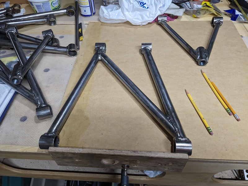
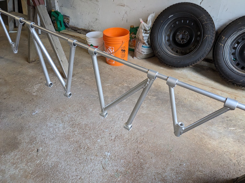
I hope these wishbones fit! What we call control arms the Brits refer to as wishbones and now that they are all fully welded time to see how the front ones fit and time to attach the brackets for the back ones – twice!
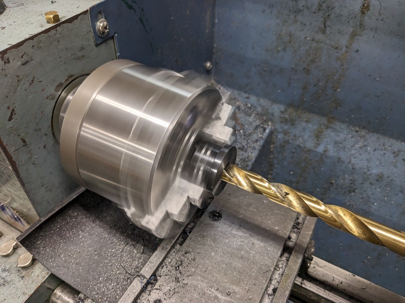
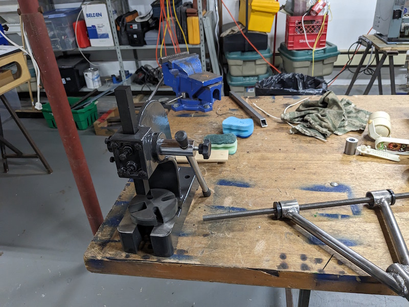
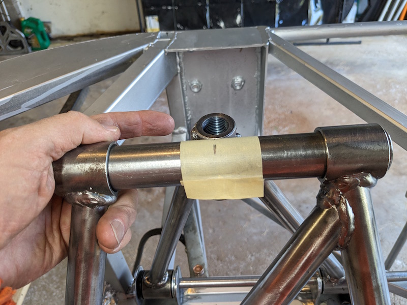
The first order of business was to center drill all the bushings to 1/2″. Ultimately the bushings will be drilled to 3/4″ there will be a crush tube (with a 1/2″ id) that will go in the bushing. For now the 1/2″ hole will locate the suspension arms accurately without the need for the crush tube. I used a small arbor press to put in a half bushing on one side of the bushing tubes. These press in “snugly” and will need to be forced out so having one end of the bushing tube open makes that a lot easier.
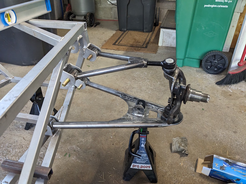
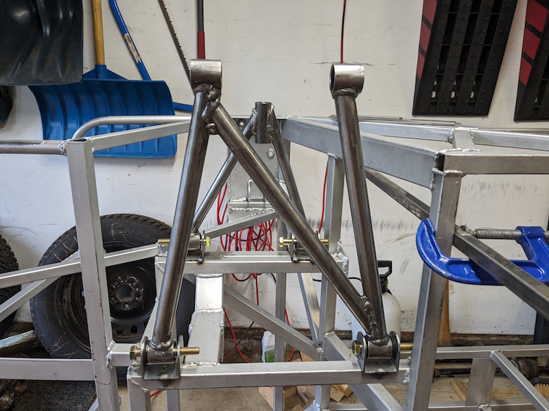
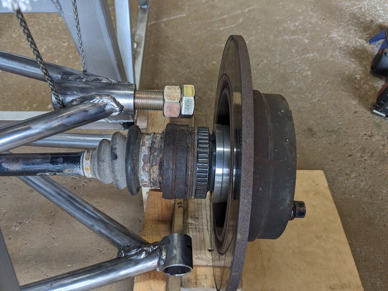
I pressed an old ball joint into the lower front control arm, threaded the top ball joint into the top arm and put it all together on the car frame. This is looking very interesting. The control arms were to match the dimensions in the book but the BMW spindle is different than the book’s donor car. Hopefully there will be enough engagement of the threaded upper ball joint into the control arm.
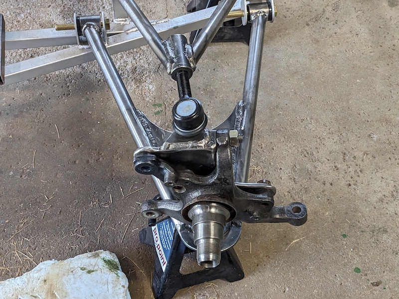
I assembled the front suspension for the drivers side and everything checked out there as well.
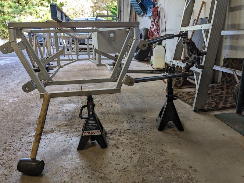
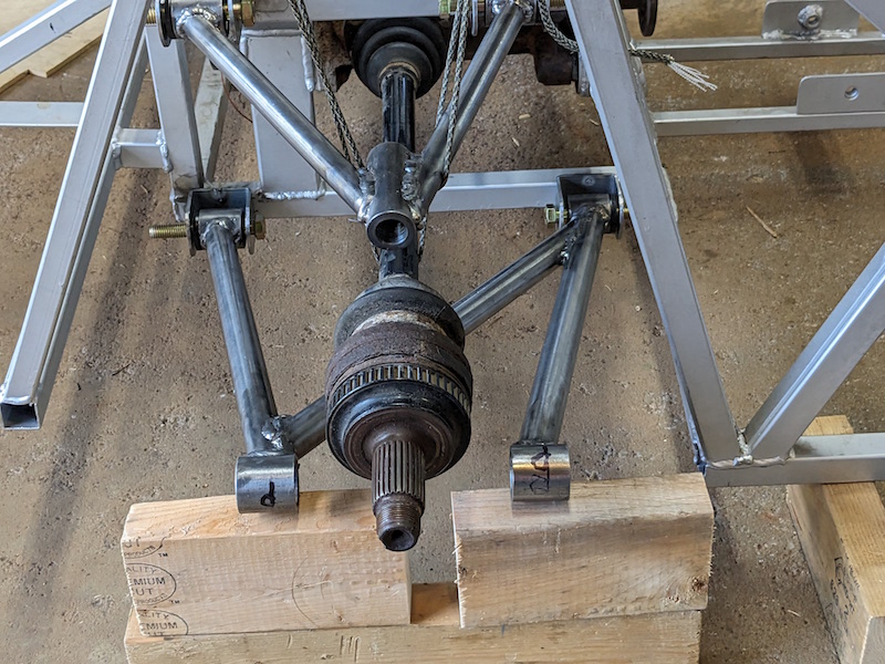
At this point the rear suspension mounting brackets had not been positioned and welded ton the frame. Since the differential differs from the doner vehicle in the book I could not just use their locations.
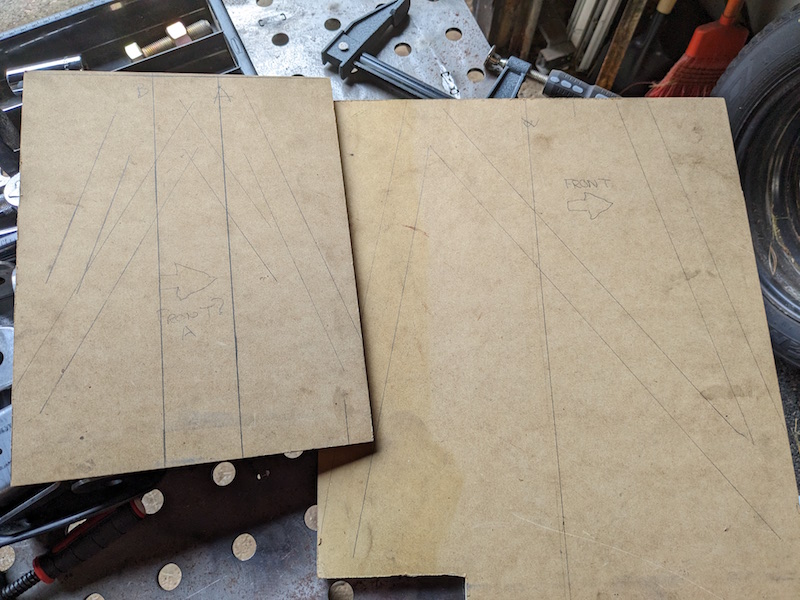
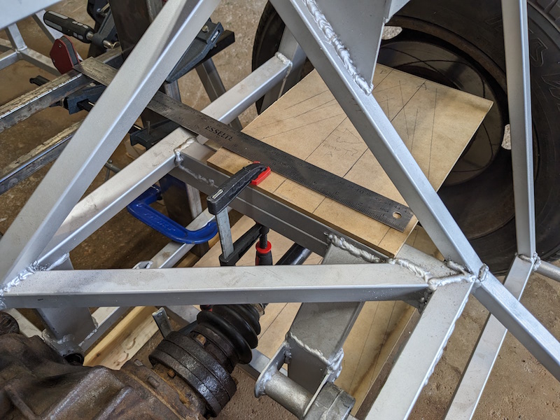
I created a couple hardboard templates to show the locations of the bracket center lines. I could clamp these onto the frame,align them with the center line of the driveshafts and mark the location of the brackets.
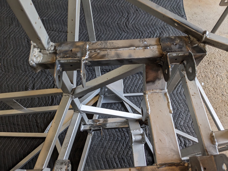
This worked out pretty well to align the brackets and control arms except for one small problem…

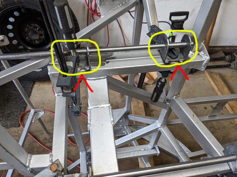
The upper control arm extends too far from the frame because I welded the brackets on the side of the upper frame member rather than the bottom surface (Arggghhhhh, I hate it when I do stuff like that…). Well I will have to think about this for a while, I have other things to do.
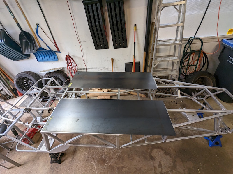
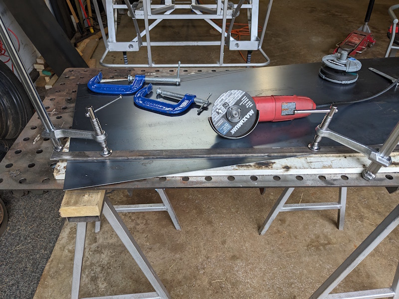
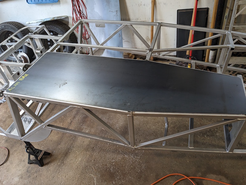
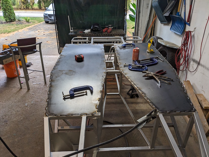
I decided to go with 16 ga. steel for the floor pans of the Locost. It is heavier than aluminum but it’s stronger and can be welded onto the frame. The added weight is located as low in the frame as possible. Rectangular sheets were measured marked and trimmed with the angle grinder.
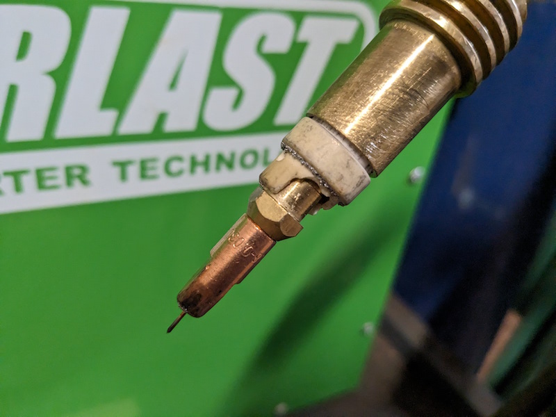
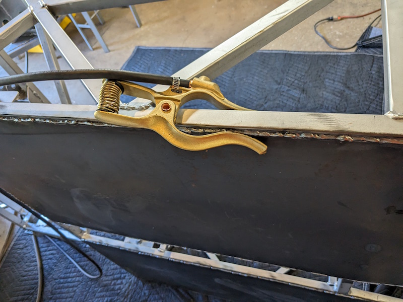
While I was getting ready to weld the floor pans I discovered an issue with the welder . A ceramic spacer in the nozzle was chipped so I made a trip to Everlast and picked up a couple along with a enhanced ground cable. I made a few passes around both of the floor pans stitching them until they were continuously welded onto the frame.
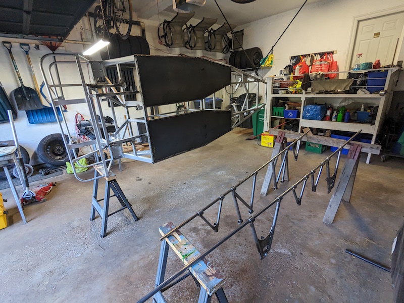
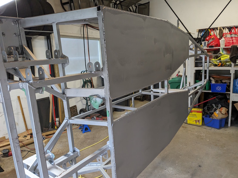
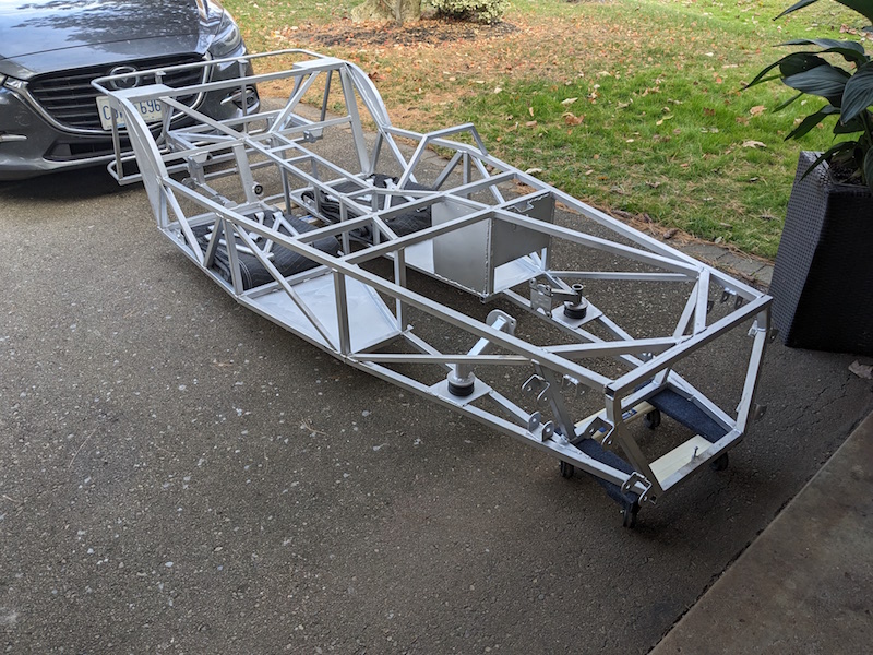
Time to get a coat of primer on all that unprotected new metal. I hung the frame up on it’s side so it would be easier to paint both surfaces of the floor pans. At the same time I hung up all the control arms to give them a coat of primer as well.
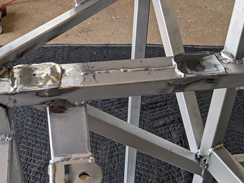
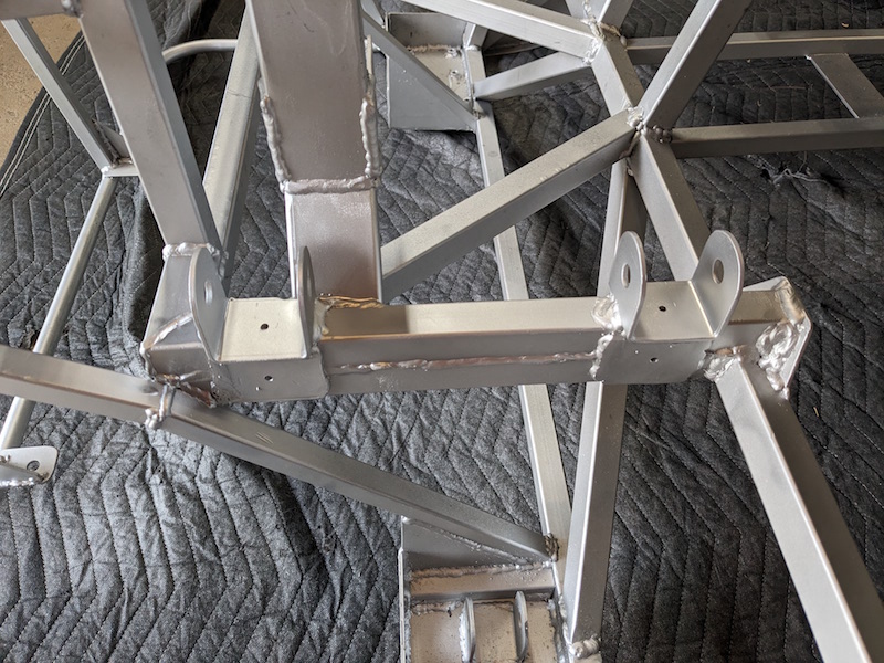
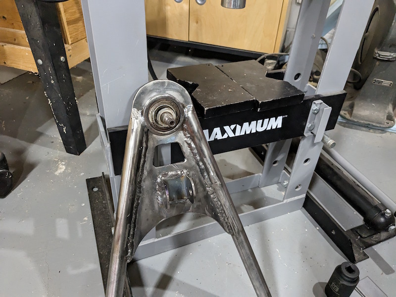
Time to fix those “miss installed” suspension brackets. I had extra brackets so I decided that the best plan was to cut the arms of the original brackets and put the brackets where they should be. Looks a bit ugly until you get a coat of primer on it !
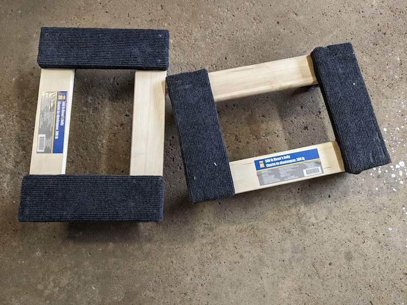
I picked up a couple moving dollies because the frame is weighing about 185 lbs so it makes it easier to move.
![]()
Starting to look like a car Nice work!