The Lo-cost front suspension uses upper and lower control arms, ball joints and a coil over shock. The BMW doner front end has a lower control arm with ball joint and and a McPherson strut for the upper connection. I need to “design” and fabricate an upper ball joint adapter to replace the strut.
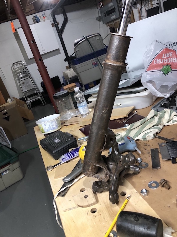
The McPherson strut as it attaches to the BMW hub.
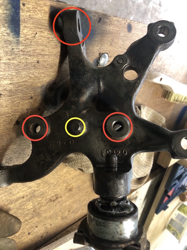
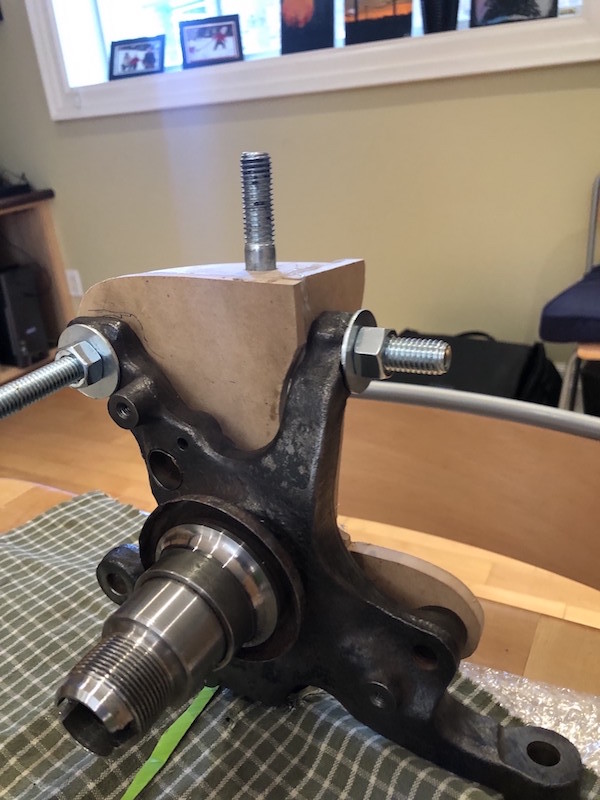
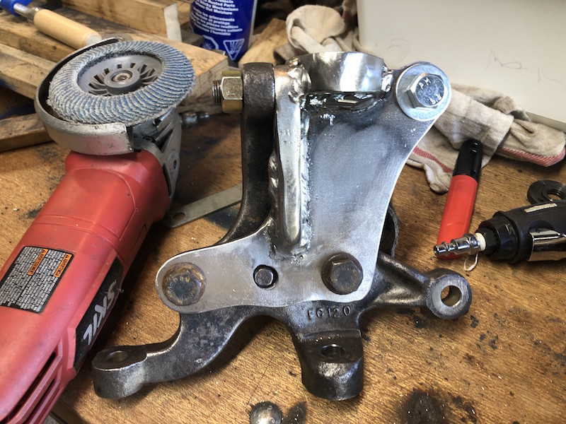
Here is the back side of the front hub with a lower ball joint in place. There are the 3 dedicated mounting points (plus a locating stud circled in yellow) for the strut. The other two mounting points are for the disk brake caliper.
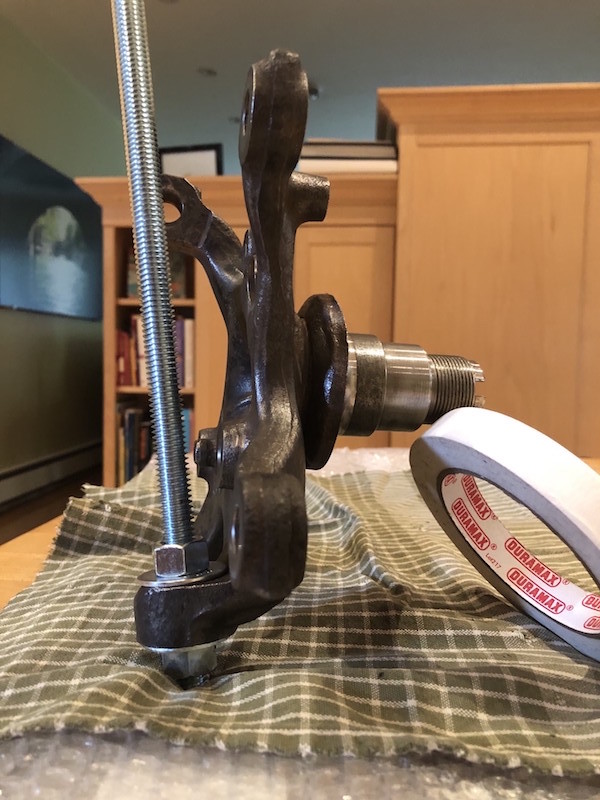
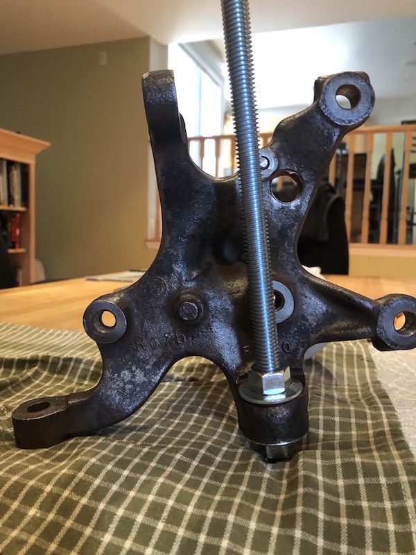
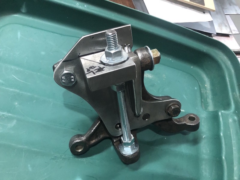
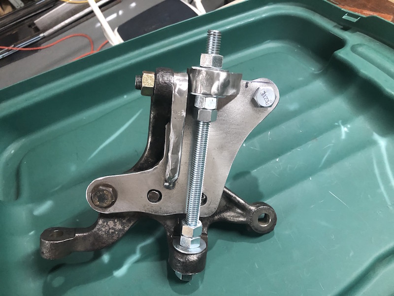
A couple views of the a hub with a threaded rod clamped through the lower ball joint boss. This rod was used as a reference for the location of the upper ball joint.
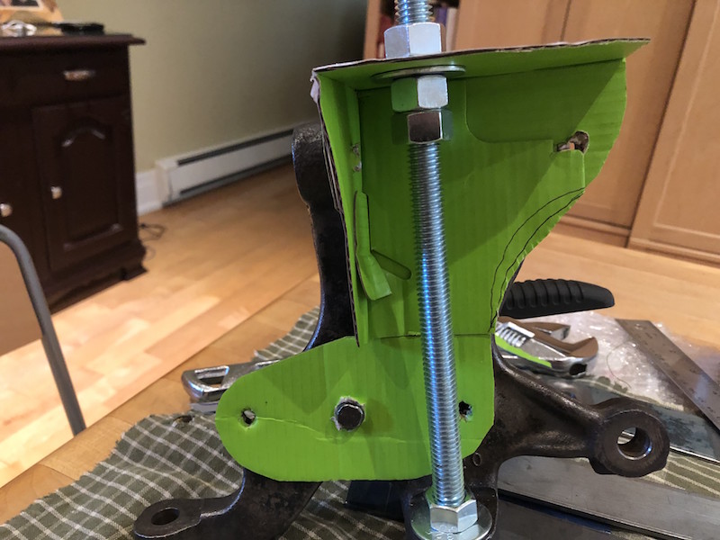
As a first step, I pieced together a cardboard mock-up of what a ball joint holder may look like.
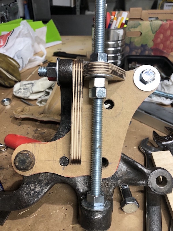
Next, I made a wooden mock up to see how a solid model with realistic material thicknesses would work. The backing plate and web are 1/4″ thick and the top deck is 1/2″ material. This holder actually bolts on to the hub in 4 places (!) using one of the brake caliper mounting holes as well. The threaded rod and nuts/washers were used to position the top plate.
A couple of views of the wooden mock-up attached to the hub. The top deck attaches to the backing plate at an angle to keep the upper ball joint in line with the lower one. The whole structure is a bit taller than I would like and the bolt that passes through the upper strut attachment boss is awkward to get at. Time for a second iteration.
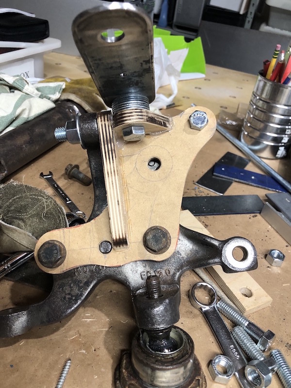
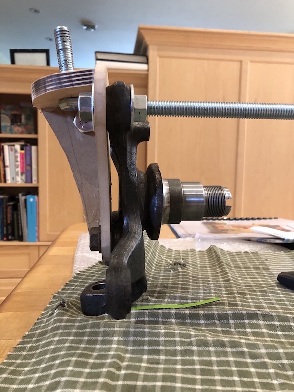
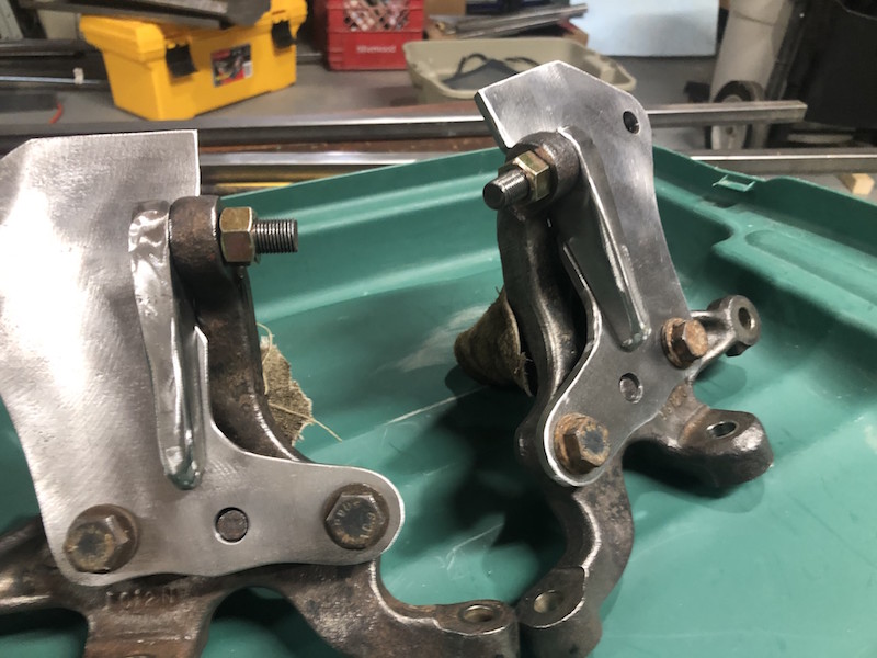
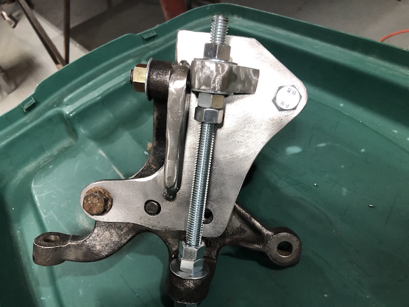
Here is the Mk II model with a lower height, a bit too low as it turns out. I need to raise it a bit to insure that the suspension arms don’t interfere with the hub during movement. On the right some washers were added to raise the control arm attachment position to check things out.
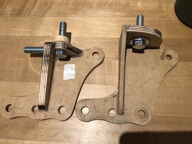
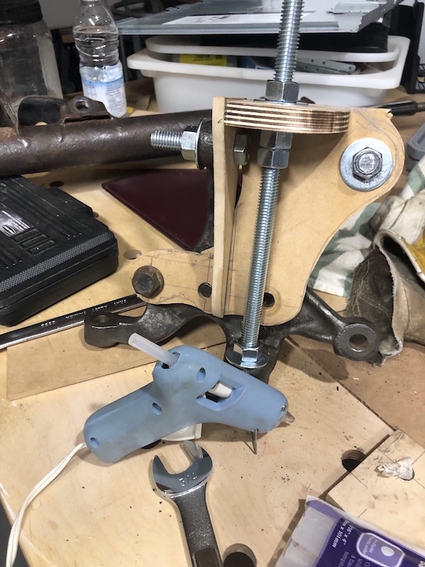
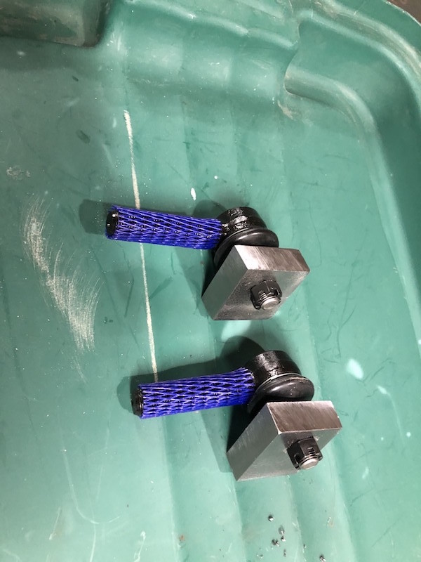
Here are the Mk I and Mk II mock ups. The Mk II is shorter and will use a stud to attach to the top boss on the hub rather than a bolt. The web is now 1/2″ thick to accommodate the stud. Wooden models are a great way to develop a complicated part. Wood is quick to cut, easy to shape, and fast to assemble using a hot glue gun.
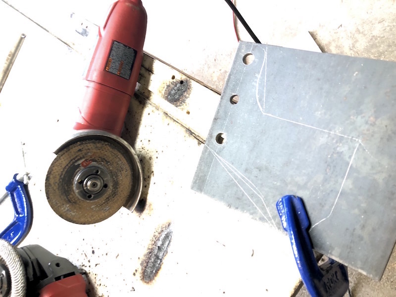
No CNC cutting here! 1/4″ thick backing plates are drilled for the bottom 3 holes and ready for cutting with the angle grinder.
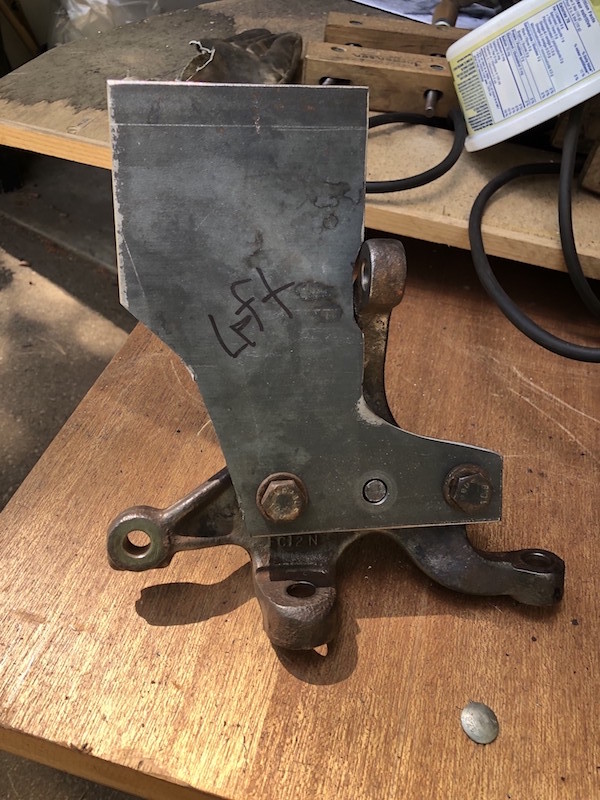
Rough cut and fitting on the hub.
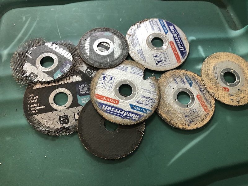
Lots of consumables later….
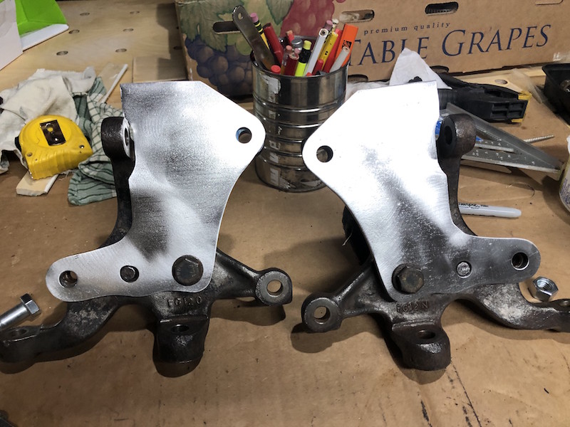
The backing plates fitted on the front hubs. They were ground to the final shape using flapper disks and a surfacing disk got rid of the mill scale. Some trimming is still required on the top but we need the web and top plate fitted first.
1/2″ plate was cut, drilled and tapped for the web.
The webs were ground to their final shape and 1/2″ studs installed. Here the back plate is attached to the hubs and the web bolted onto the upper boss.
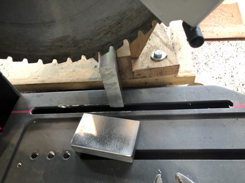
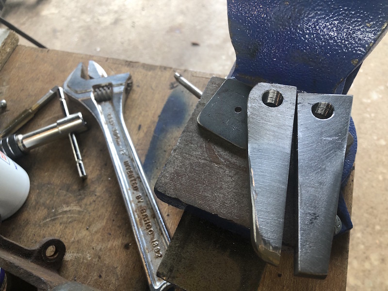
Creating the top plate was more of a challenge. They are going to be 3/4″ thick to provide a suitable depth for the ball joint taper. The chop saw cut the 3/4″ plate to the correct angle to meet the back plate. That saw is amazing!
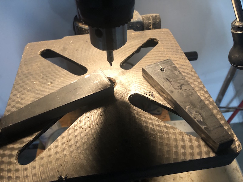
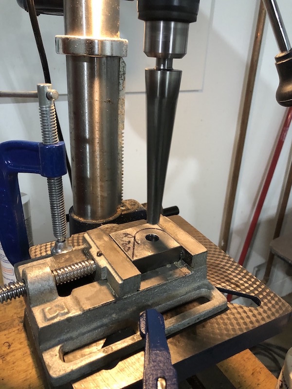
The top plate hole position was carefully measured, marked and drilled. Now the threaded rod, nuts and washers can be used to set the position of the top plate. The top plate is marked to be trimmed to the final shape.
A tapered ream was used to open up the hole in order to match the taper on the ball joints.
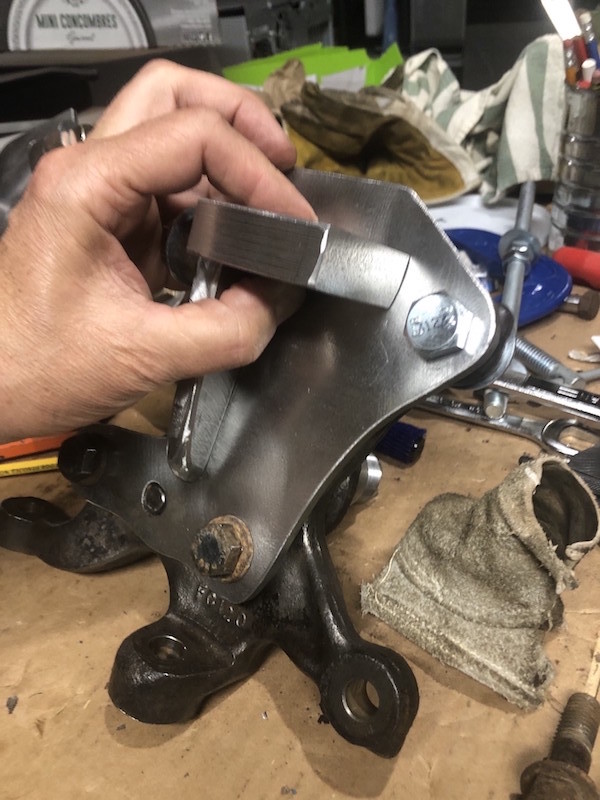
With the top plate cut and ground to shape I could determine exactly where to trim the top of the backing plate.
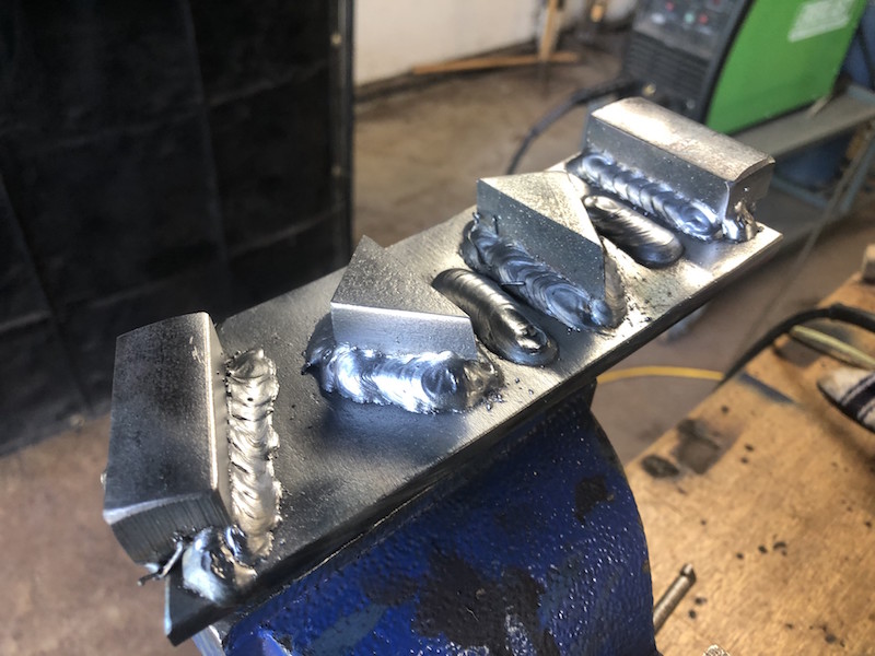
A few practice welds on some heavy plate and the ball joint adapters get fully welded.
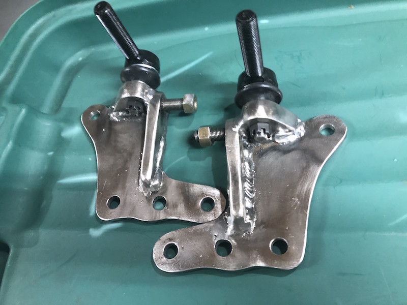
The finished product is pretty compact and looks massively strong. In the Lo-cost design the upper control arm is not constrained, the coil over shock attaches to the lower control arm. This means that the lower ball joints carry the weight of the car and the upper ball joints see much less load.
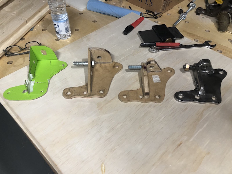
The progression from origami to finished component!
![]()
The plates look very good! Thats a lot of grinding!