040 A seat at the table (June 2023)

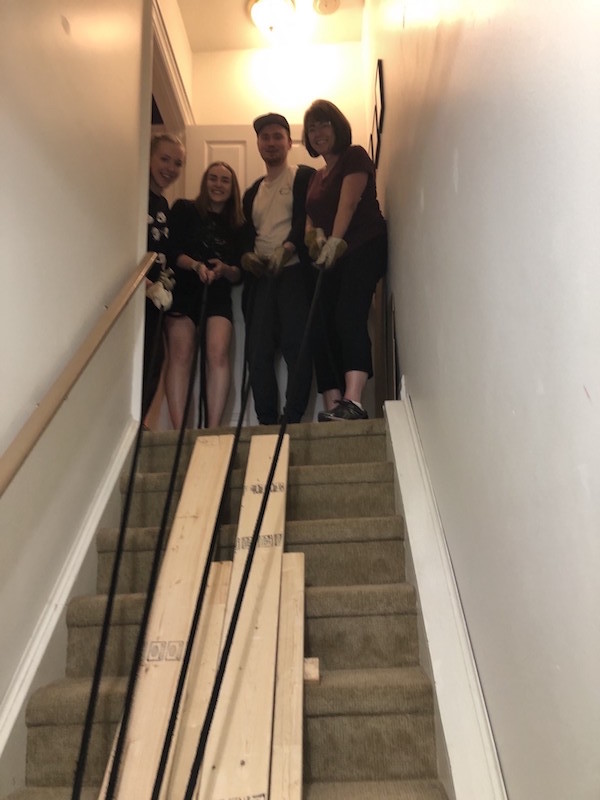
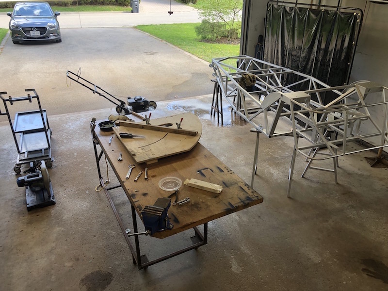
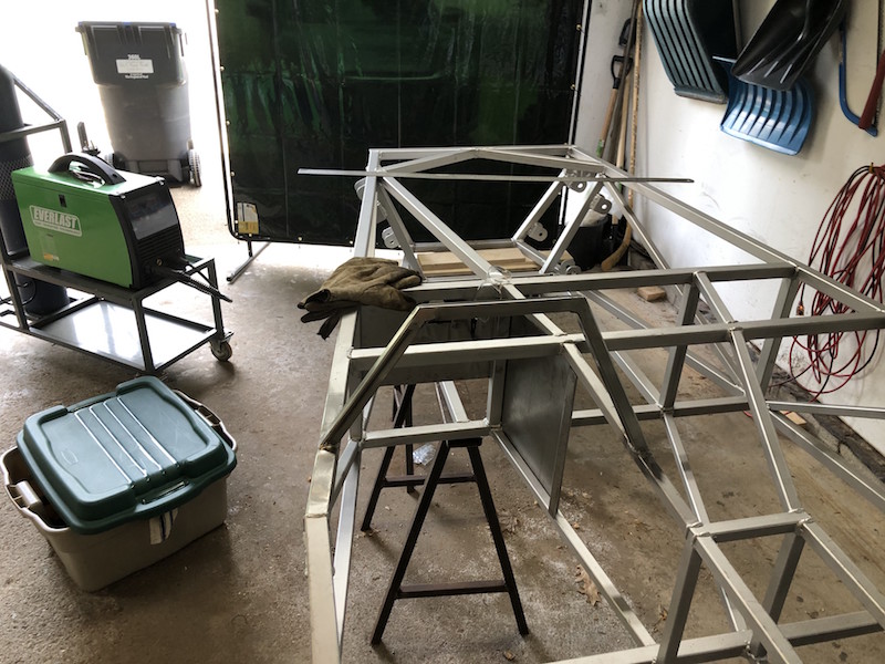
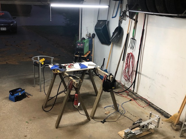
This is my original welding table, an old piece of particle core sheet on a couple even older sawhorses. Needless to say this is not ideal, getting a good ground on smaller work pieces is challenging and constantly putting out fires is distracting. When the CertiFlat 2’x4′ welding table went on sale at Princess Auto I rushed out and bought one

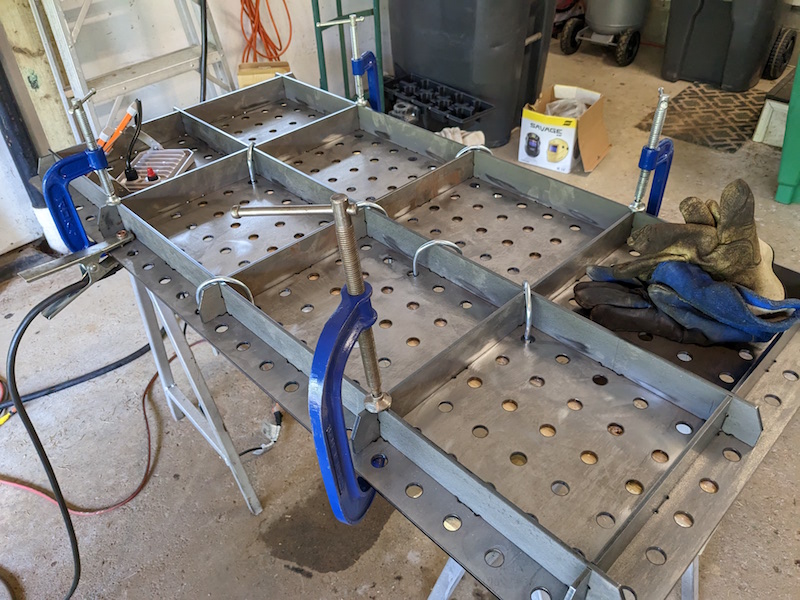
All the table parts are laser cut for a perfect fit. The procedure is to lay the top, with the crown down, on a table or across a pair of sawhorses. The lattice of support beams are then arranged on what will be the bottom surface of the table. There are tabs on the beams and slots in the table top that they engage with. U-bolts (and some clamps) are used to draw the table top onto the support beams at all intersections. The beams are then tacked onto the bottom surface of the table top. The table can now be flipped over and checked for flatness.

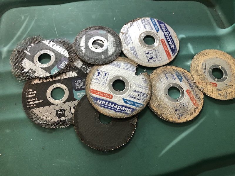
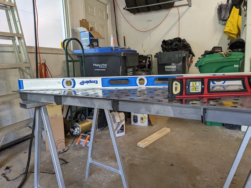
All the tabs and slots are now welded and any welding lumps created are carefully ground off. The table weighs about 100 lbs. which is not massive but flatness is maintained by the rigid perfectly straight beam structure under the top rather than by the thickness of the top. Very clever.

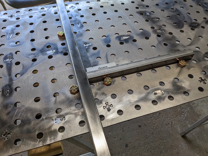
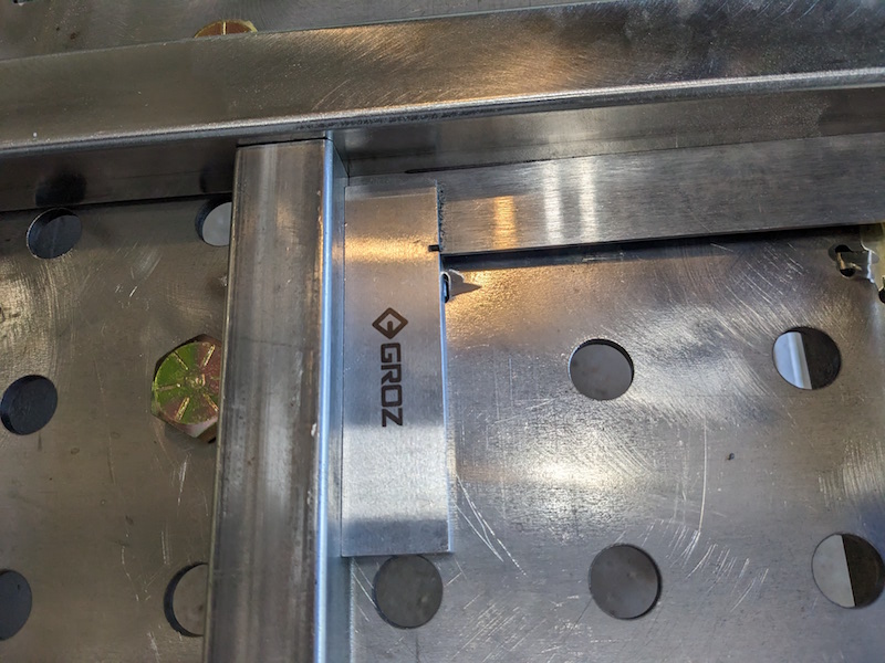
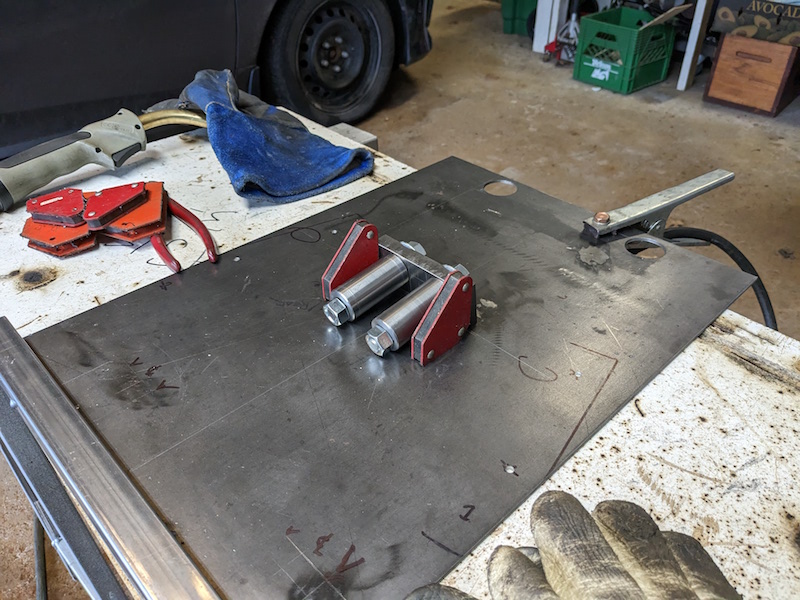
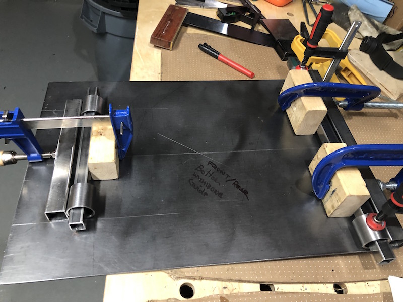
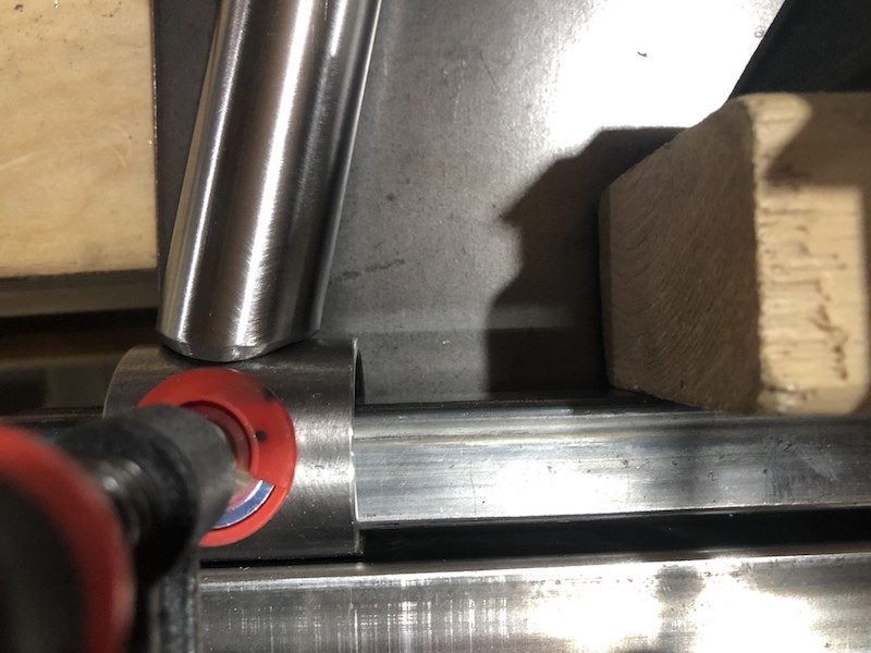
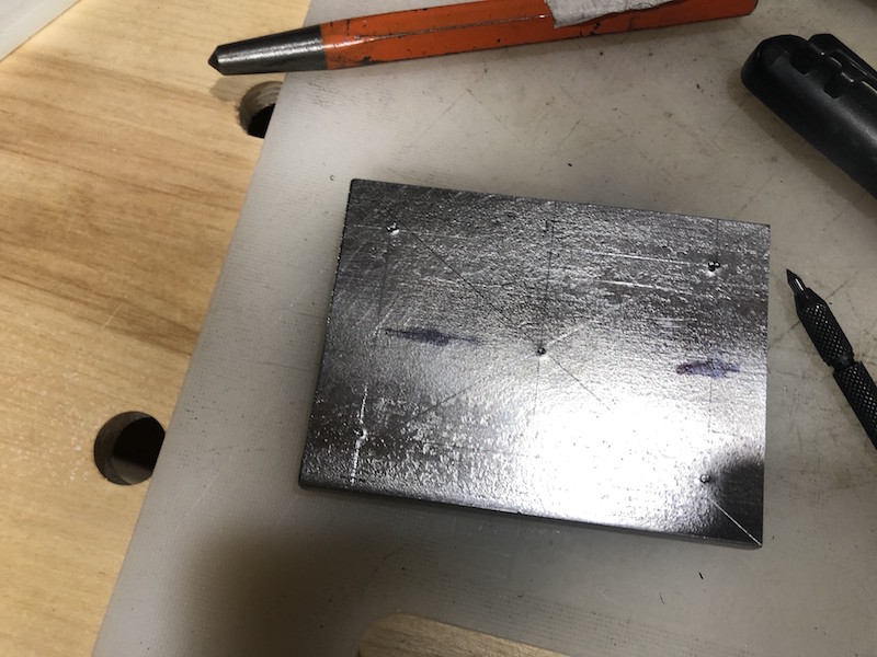
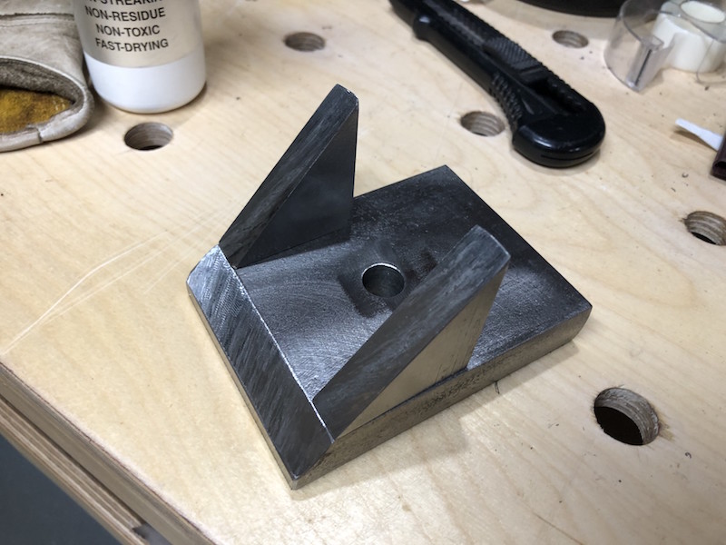
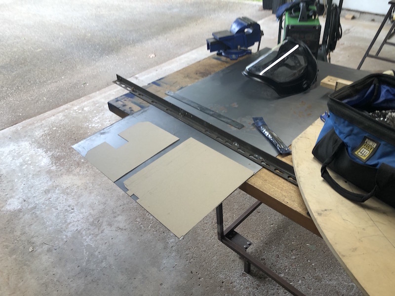
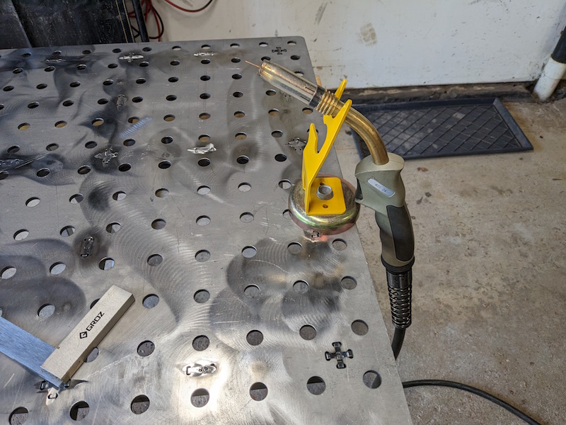
Because the hole pattern in the top is very accurately cut fixtures can be used to simplify set-up and fabrication. Some 3/4″ bolts dropped through holes in intersecting rows creates a perfect 90 degree angle. The holes can also be used to locate clamps anywhere on the surface. Time to make some fixtures.

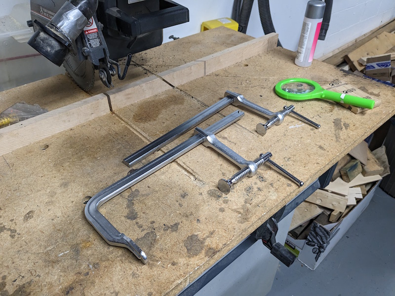
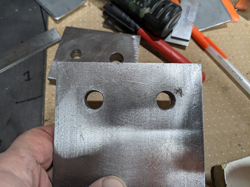
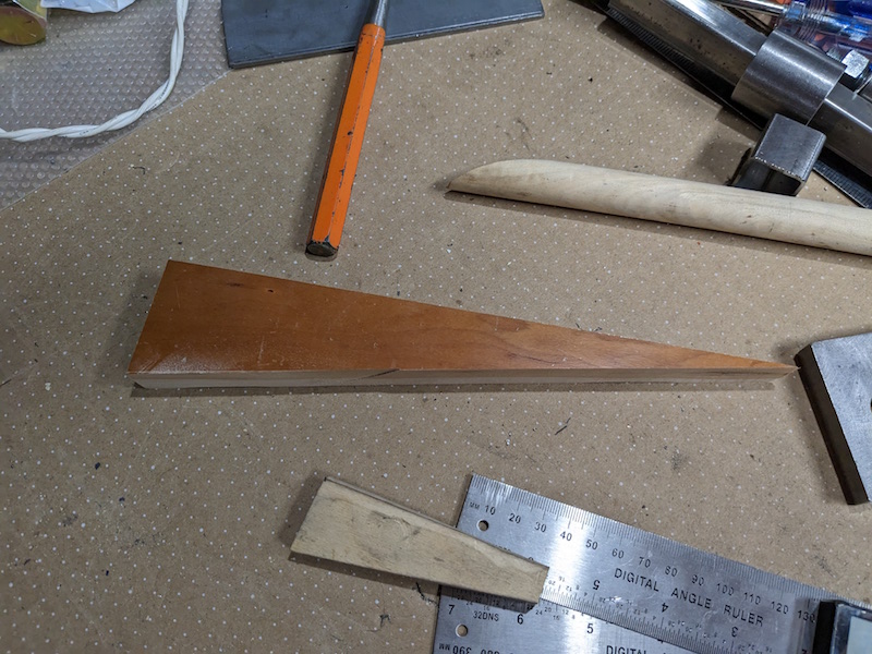
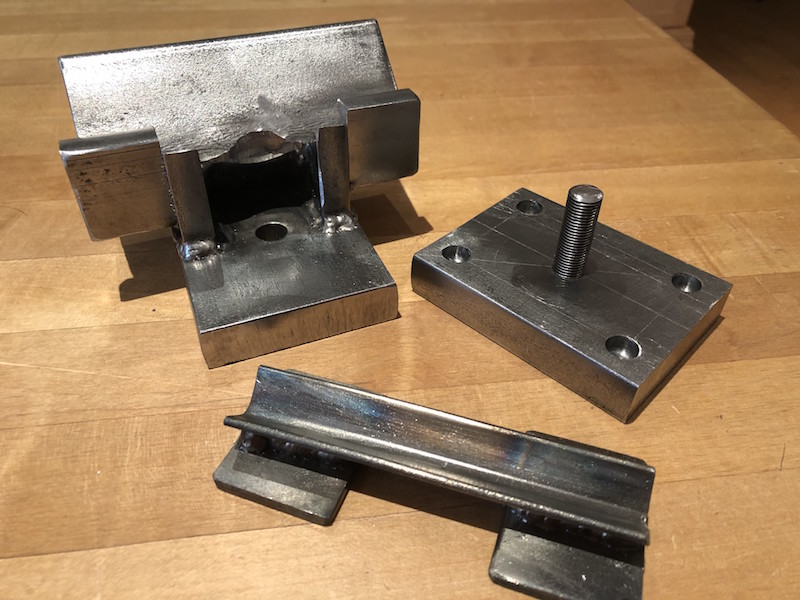
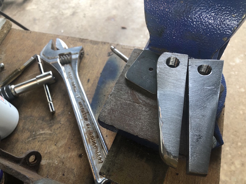
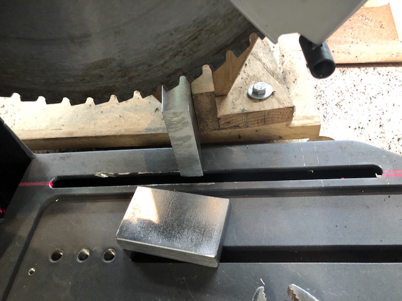
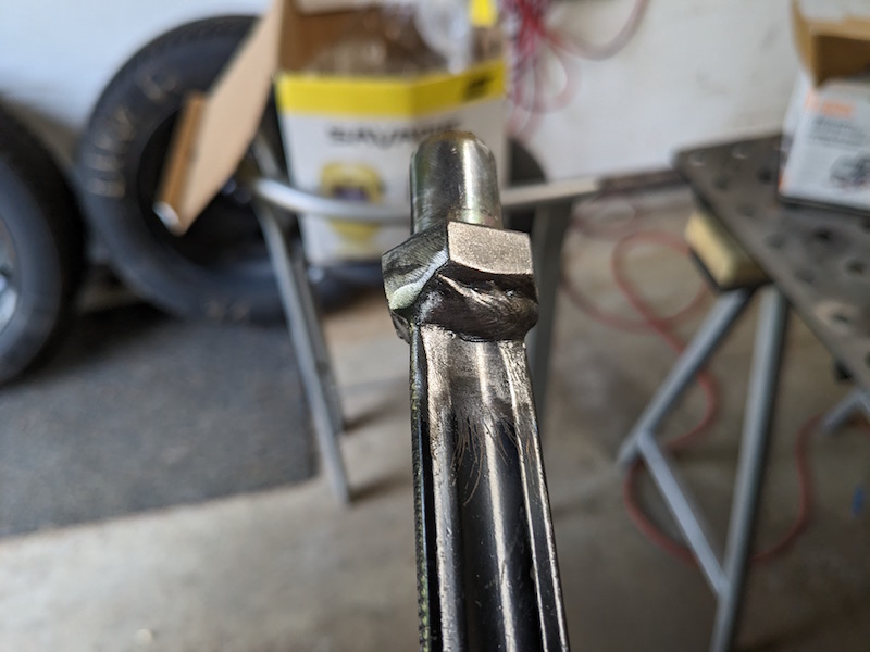
I cut the foot off of a couple heavy welding clamps, welded a 3/4″ bolt on the end and then chopped off the threaded piece.

These can now be put in an hole on the table and used to clamp a work piece.

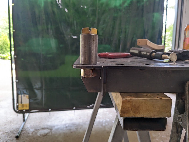
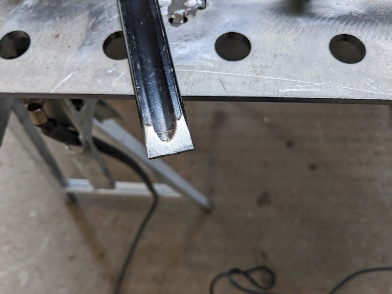
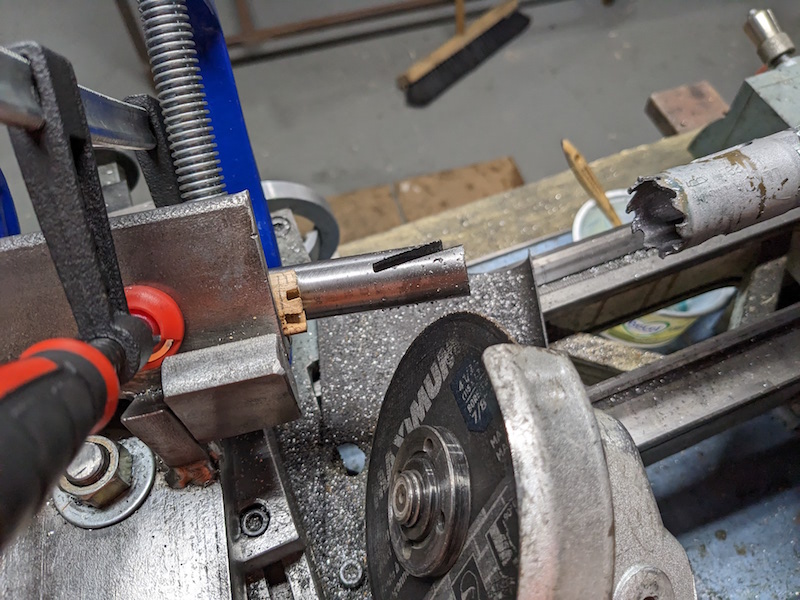
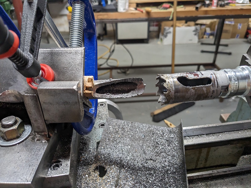
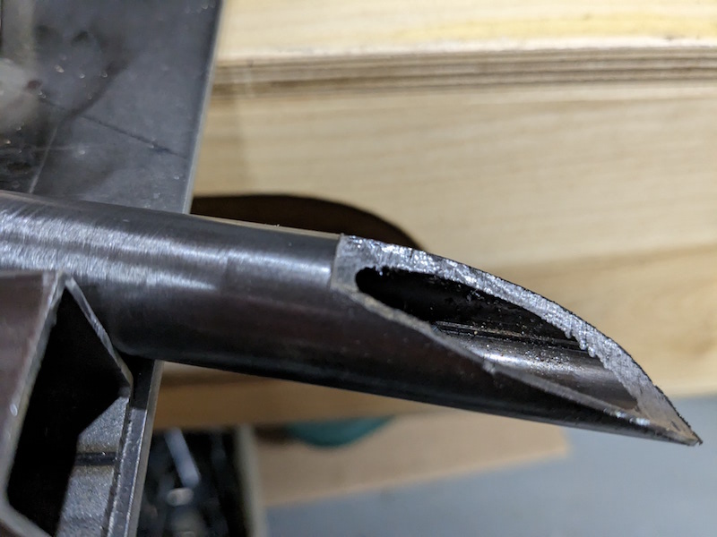
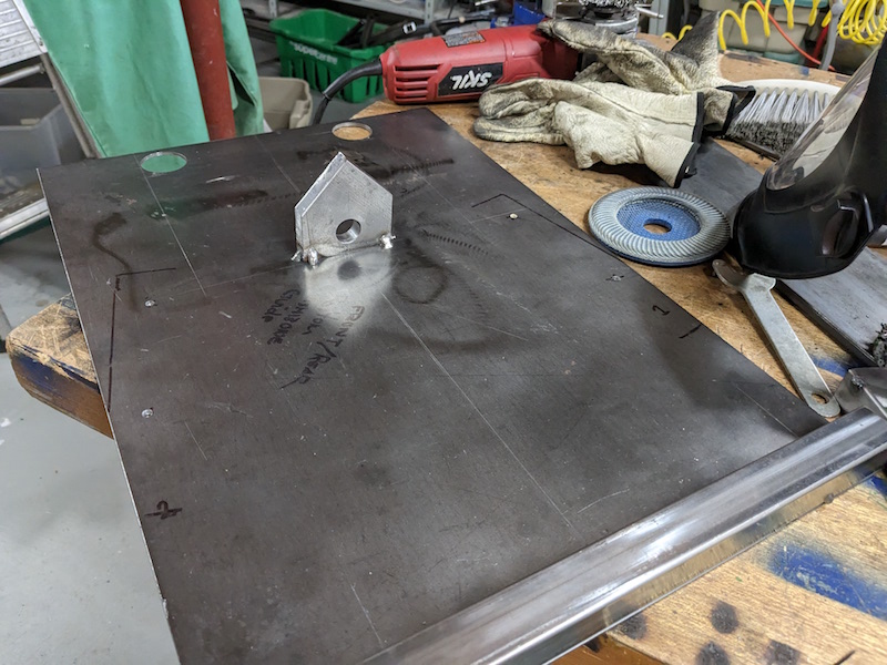
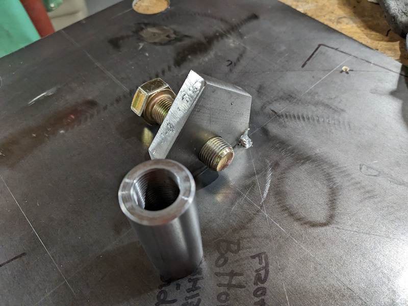
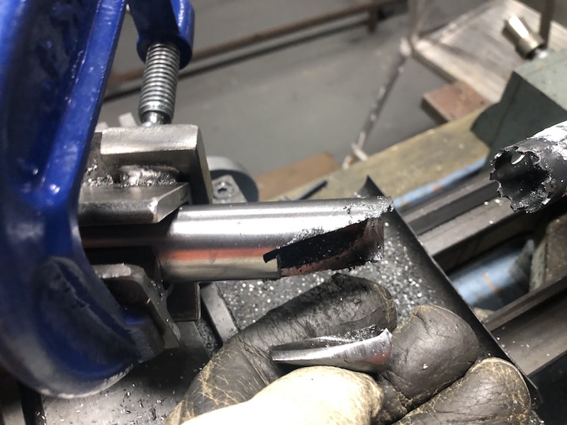
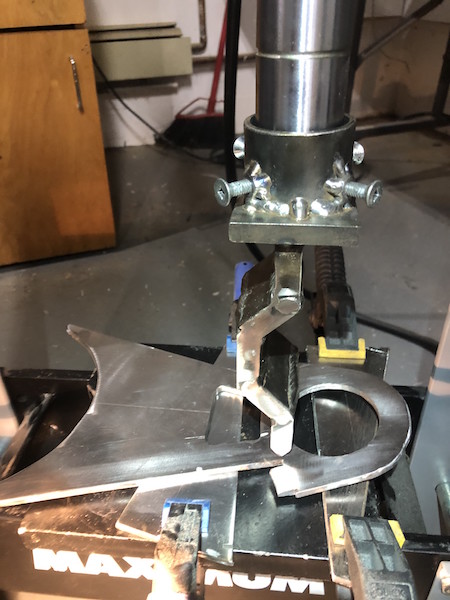
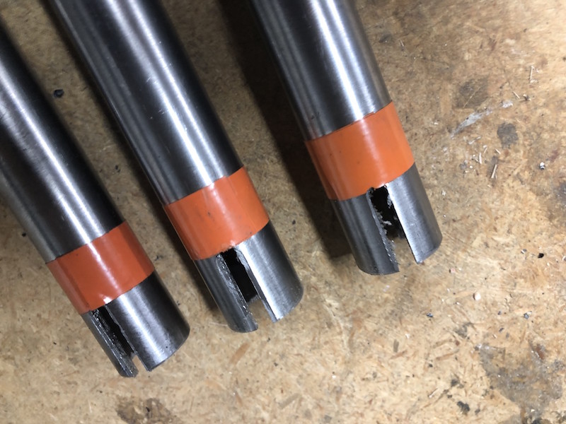
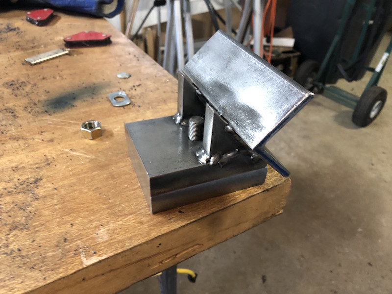
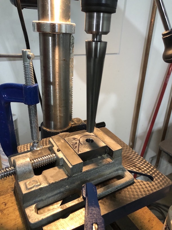
A handful of the Harbor Freight clamps volunteered for welding table duty as well. The mechanics are a bit different, a slot is cut in the bolt head, the end of the clamp thinned and welded into the slot.

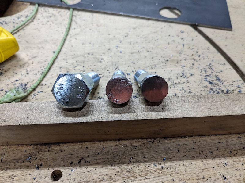
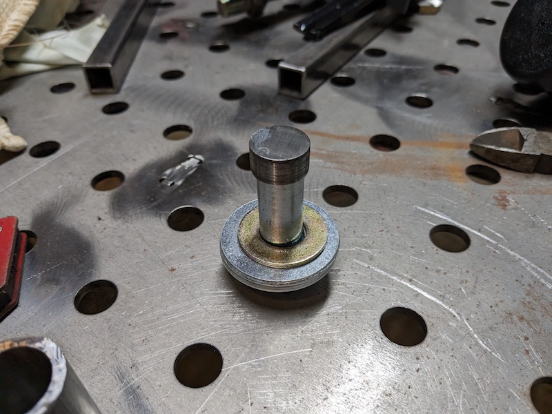
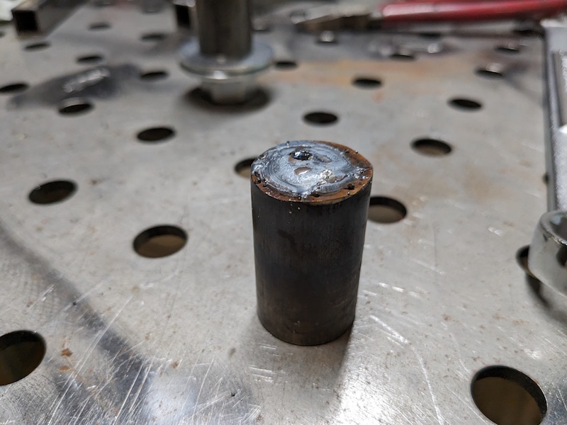
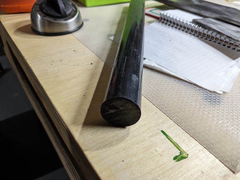
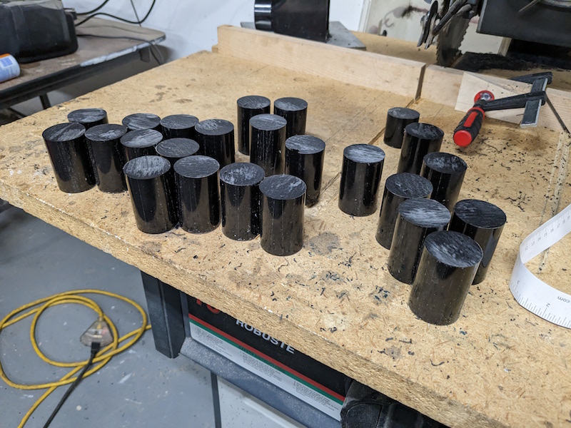
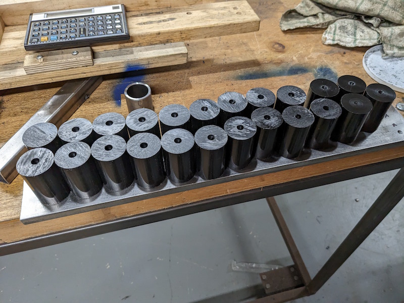
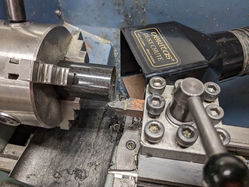
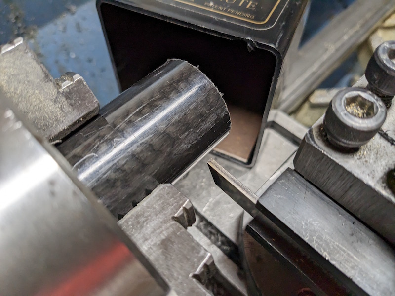
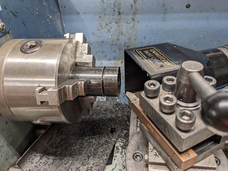
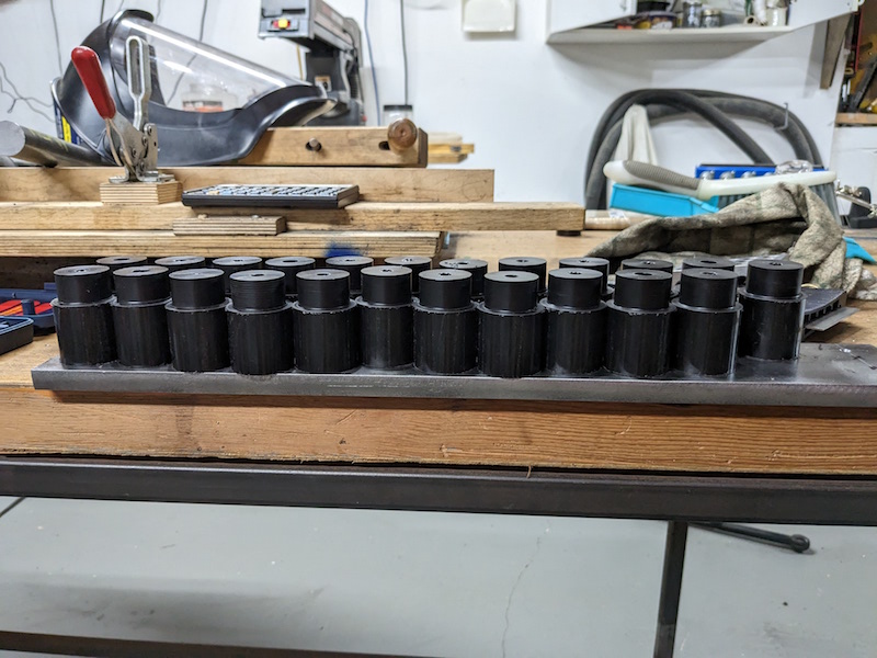
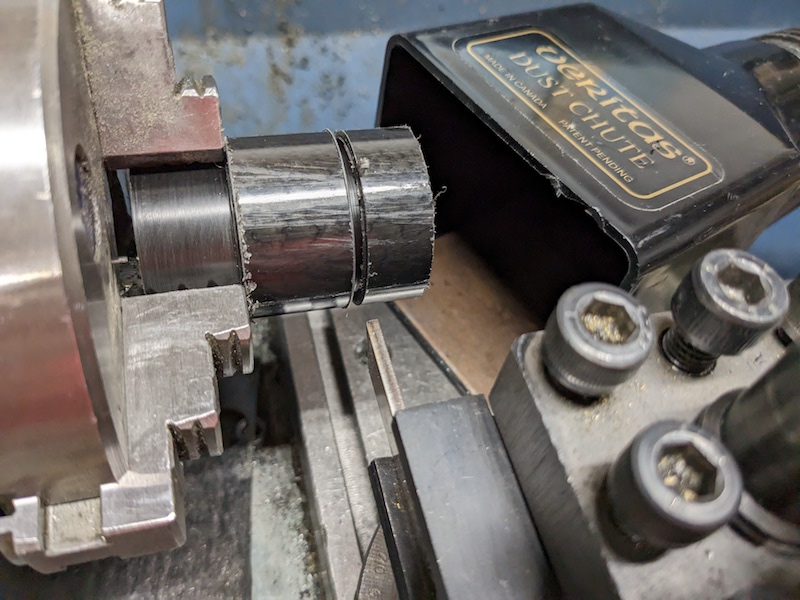
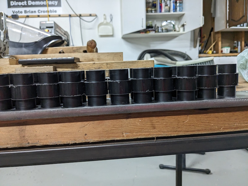
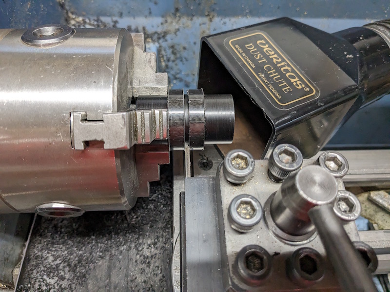
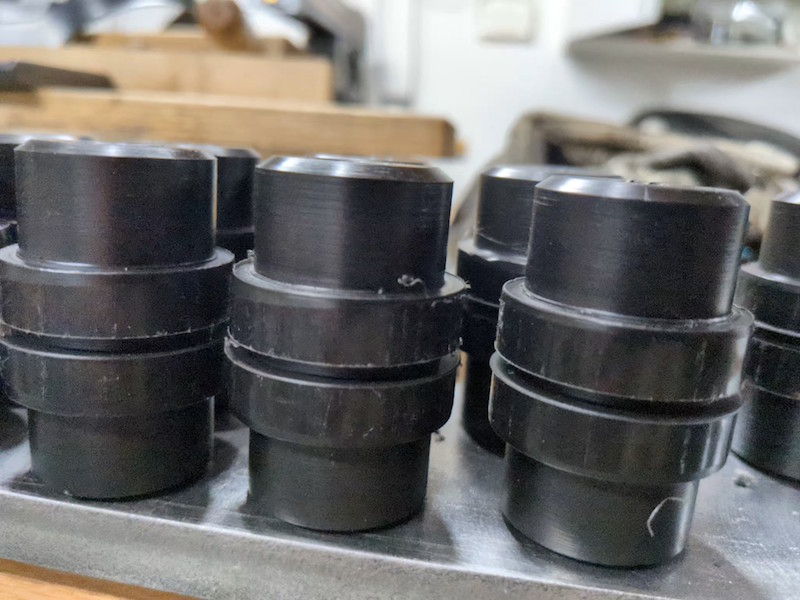
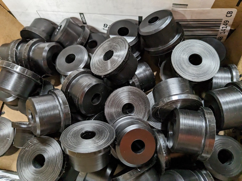
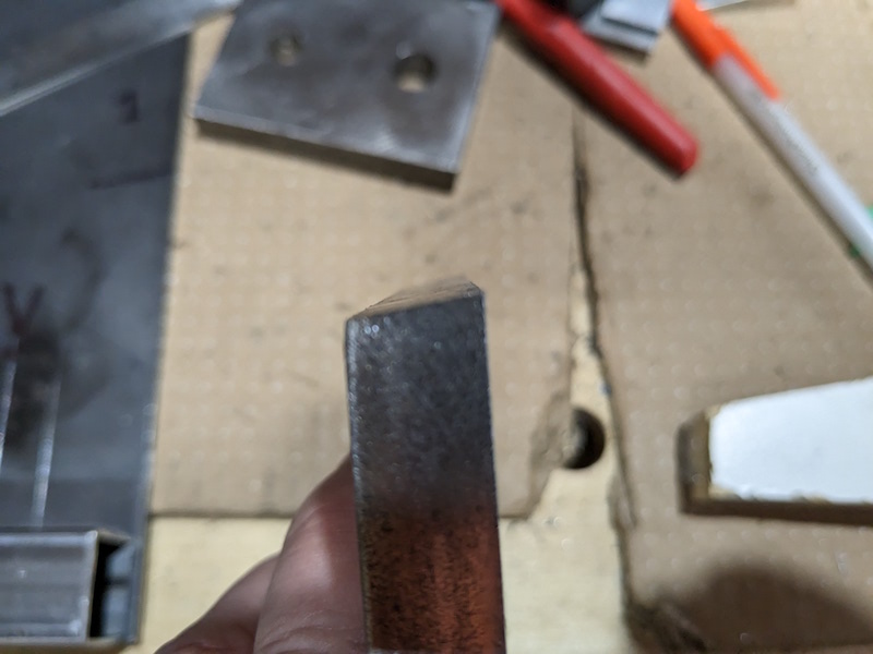
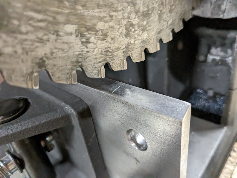
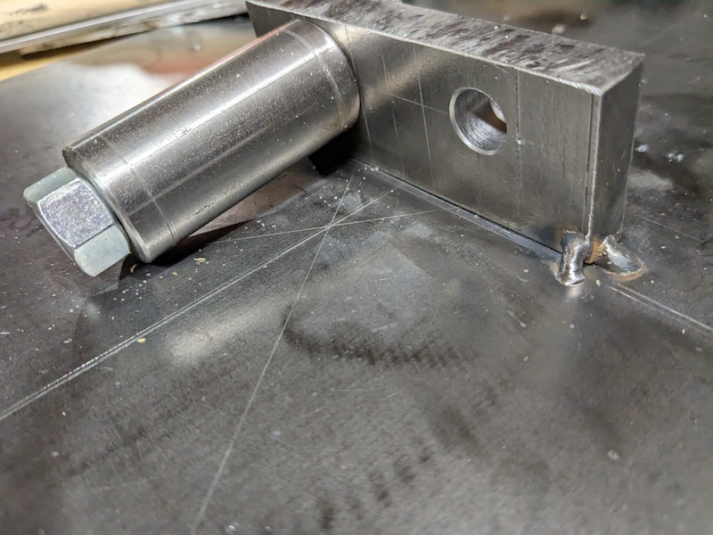
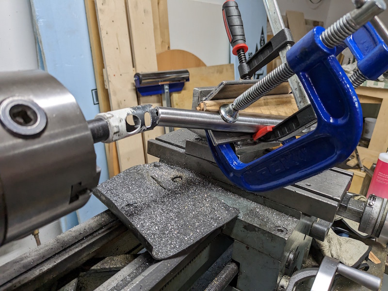
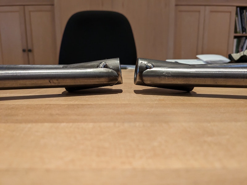
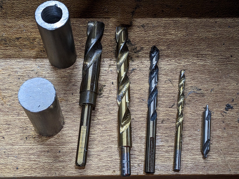
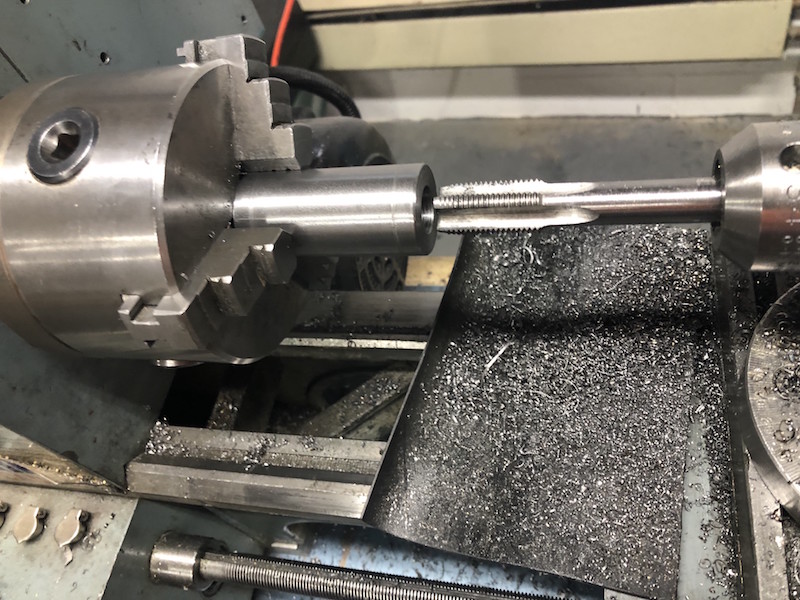
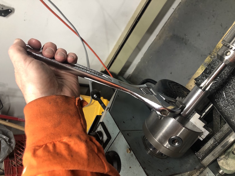
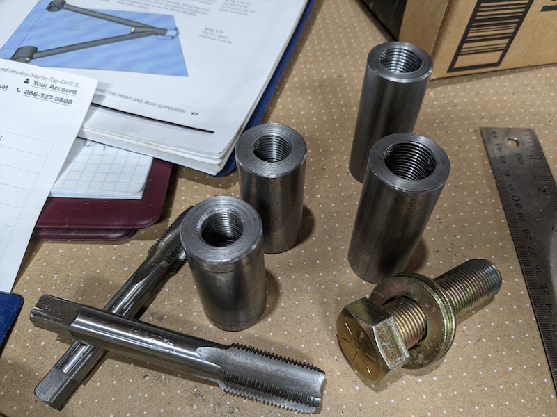
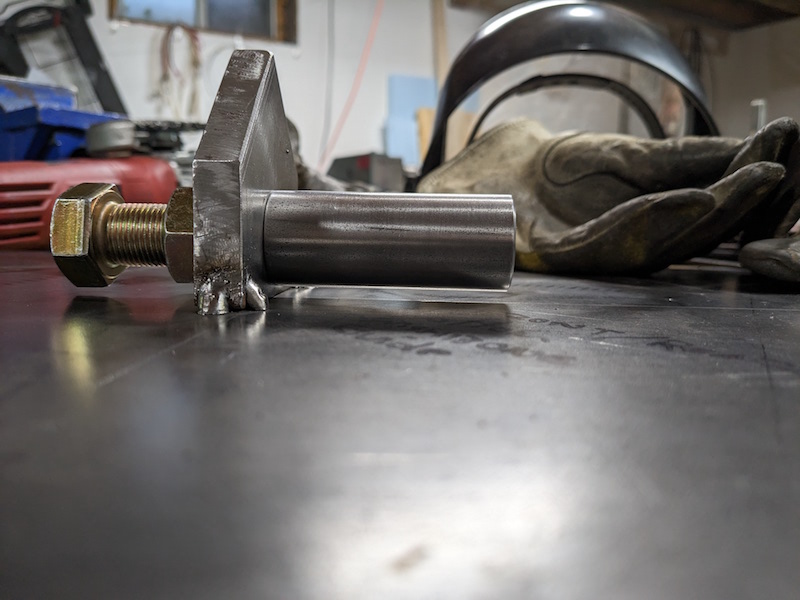
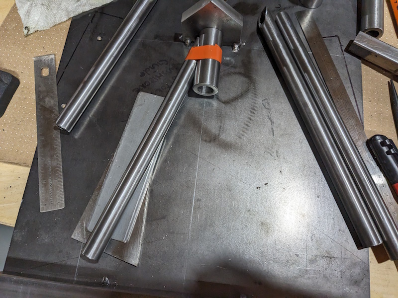
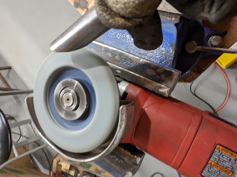
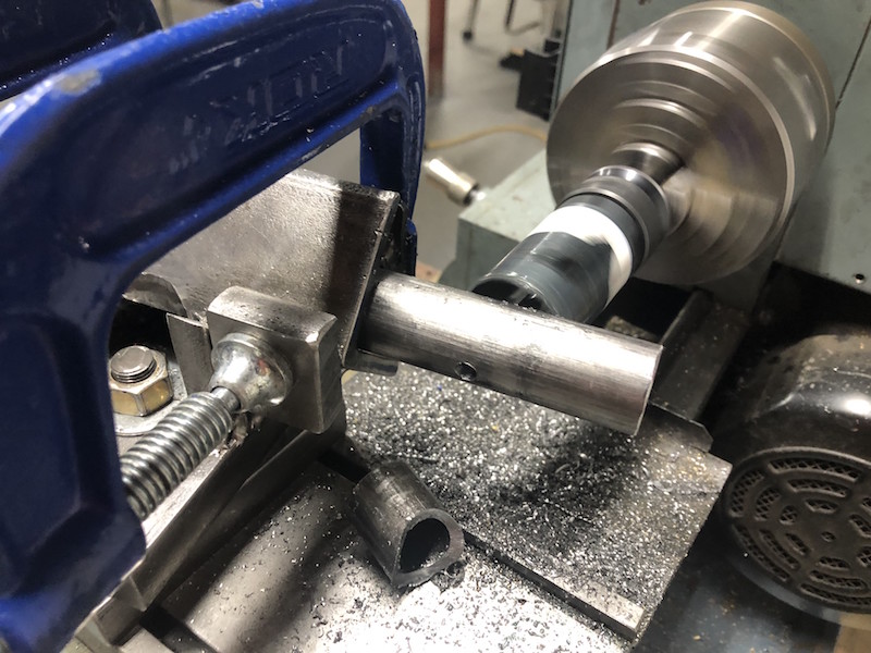
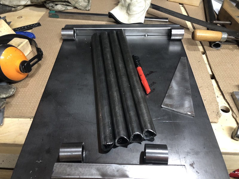
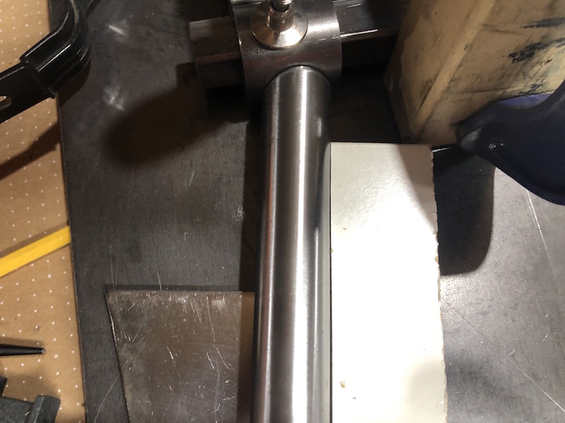
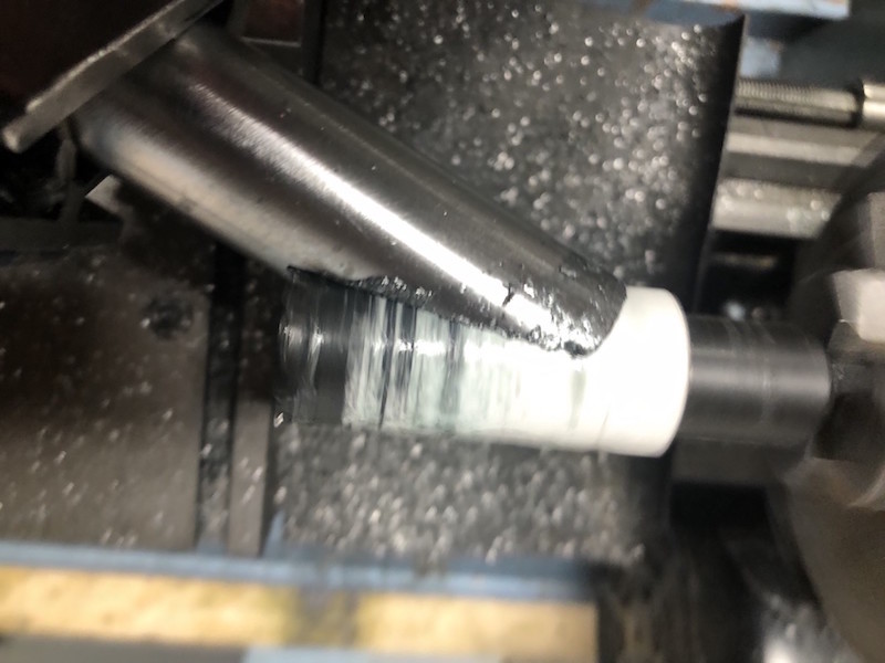
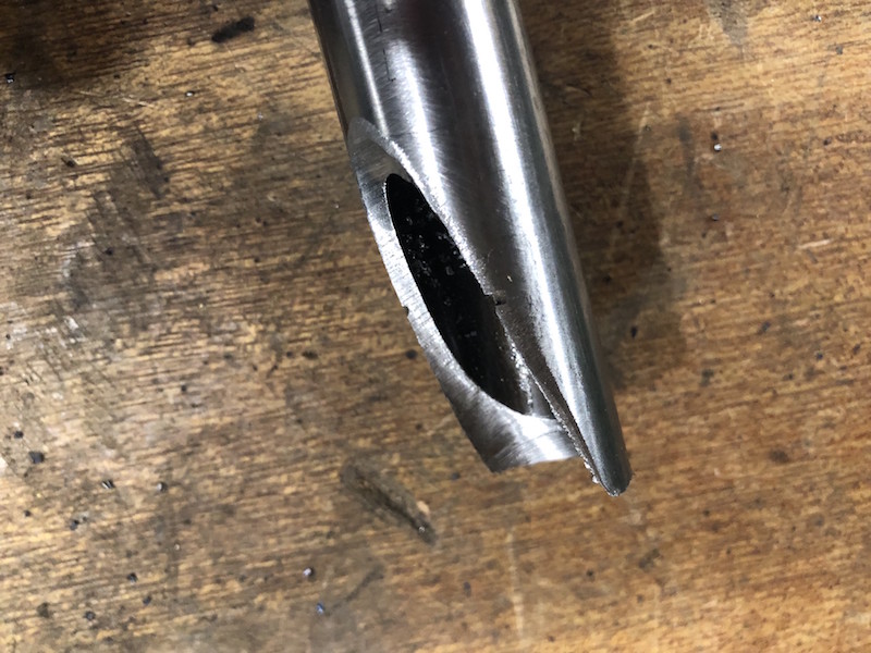
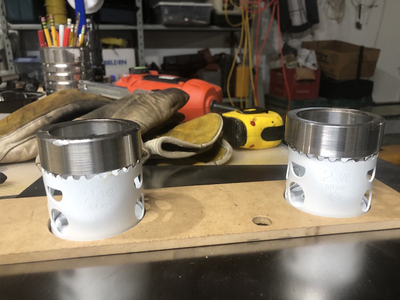
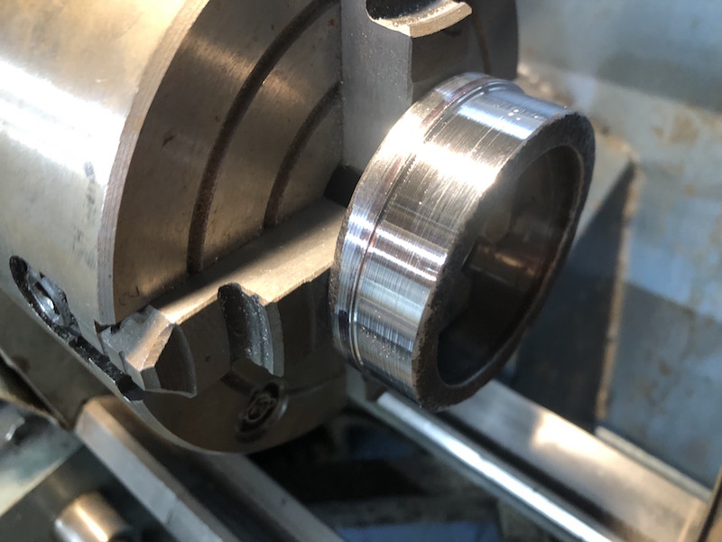
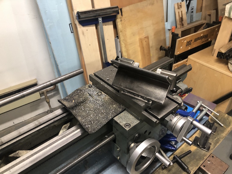
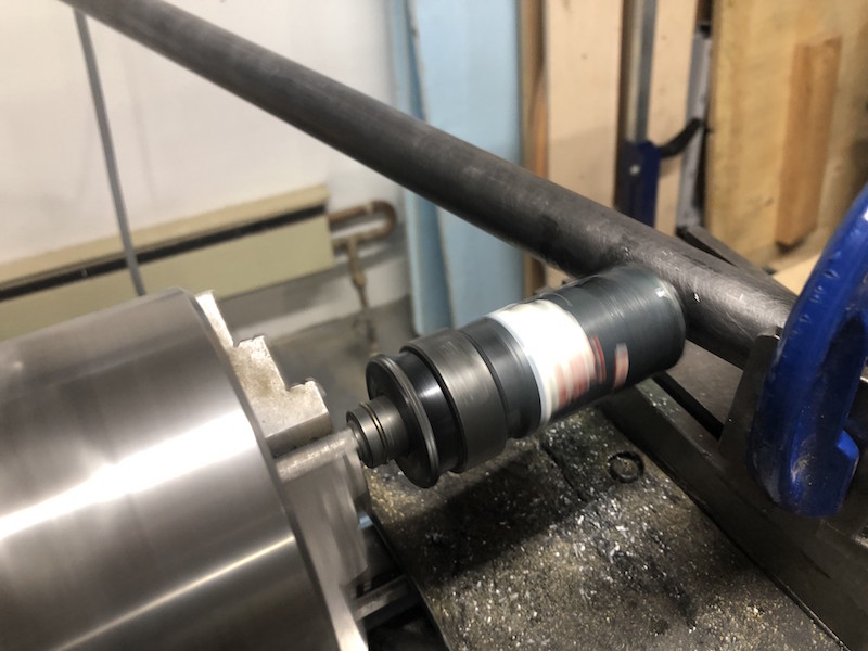
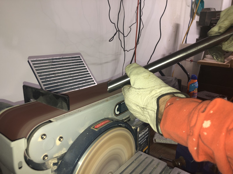
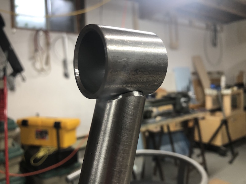
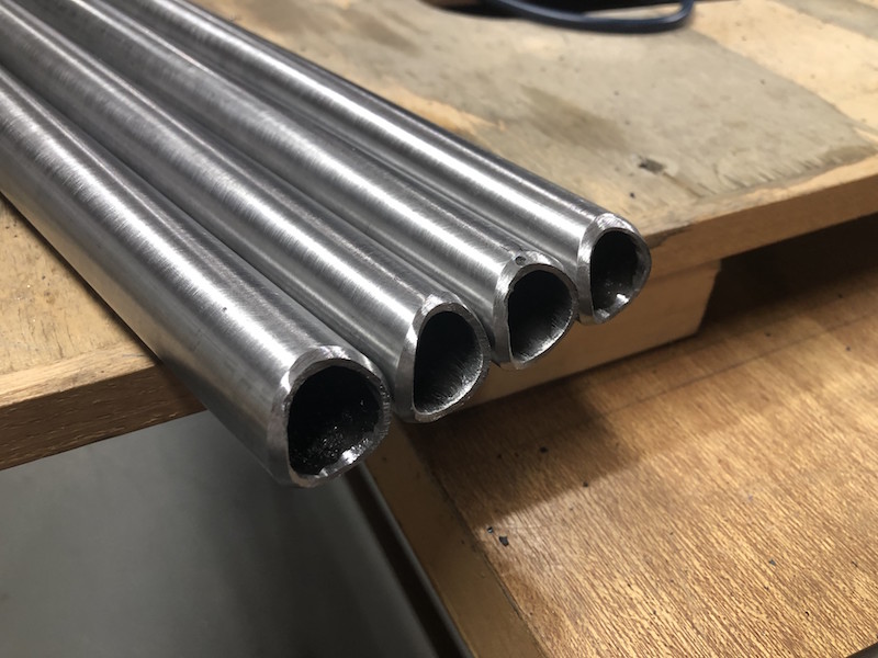
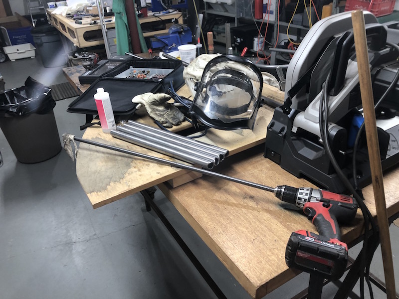
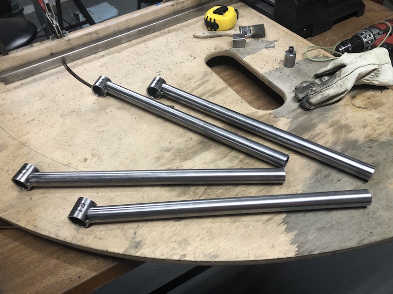
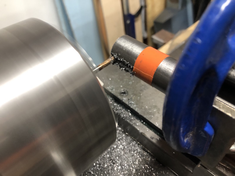
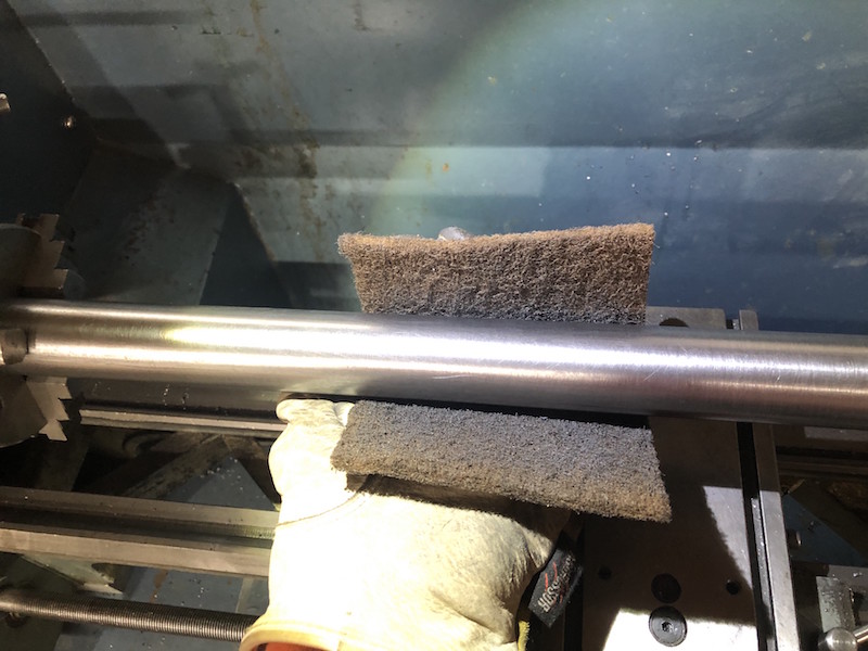
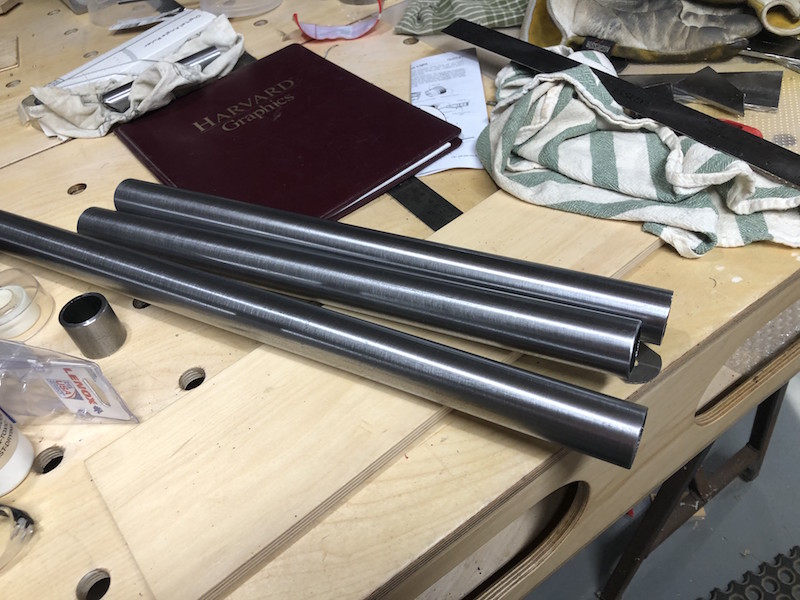
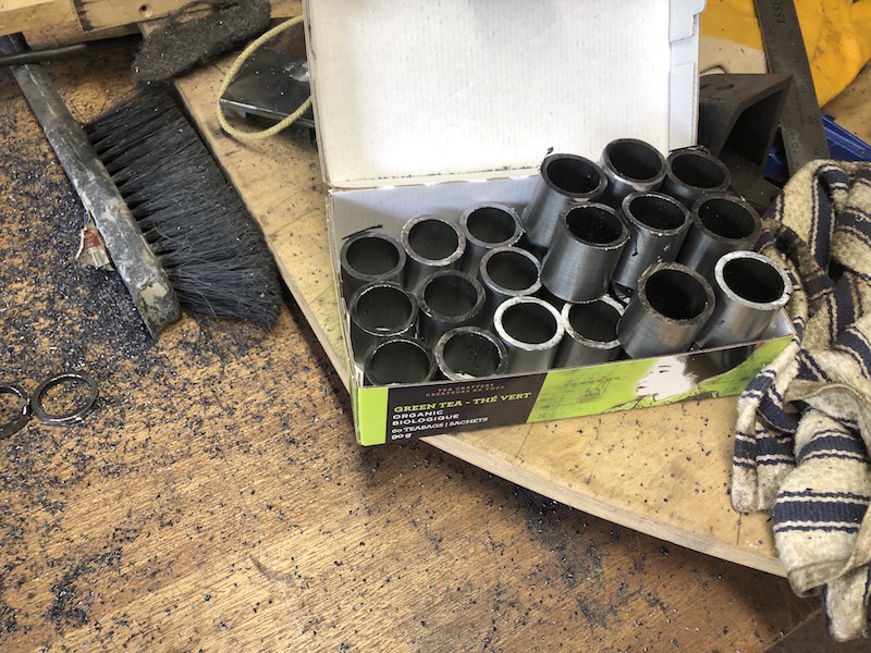
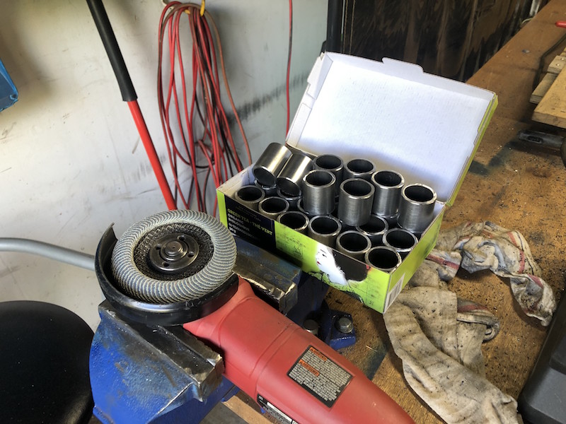
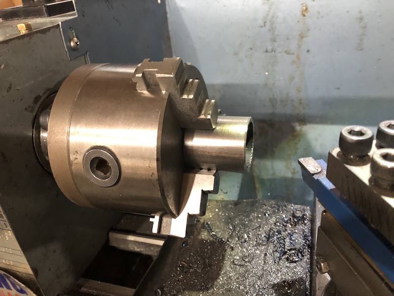
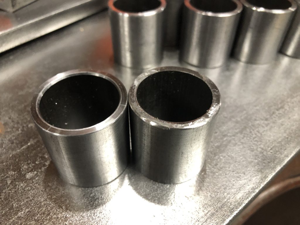
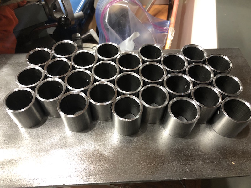
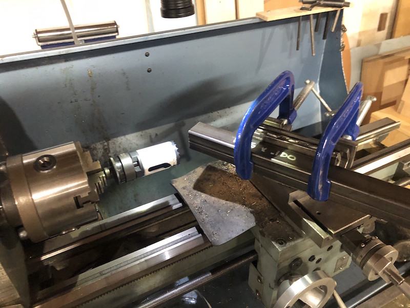
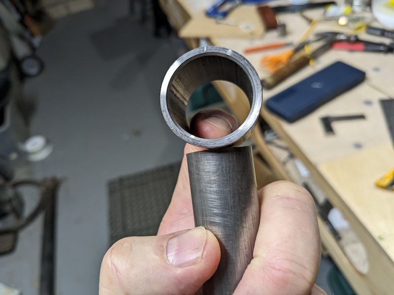
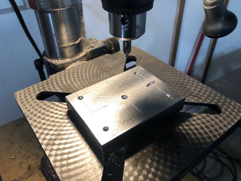
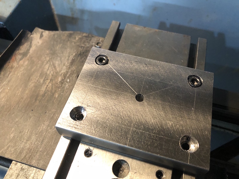
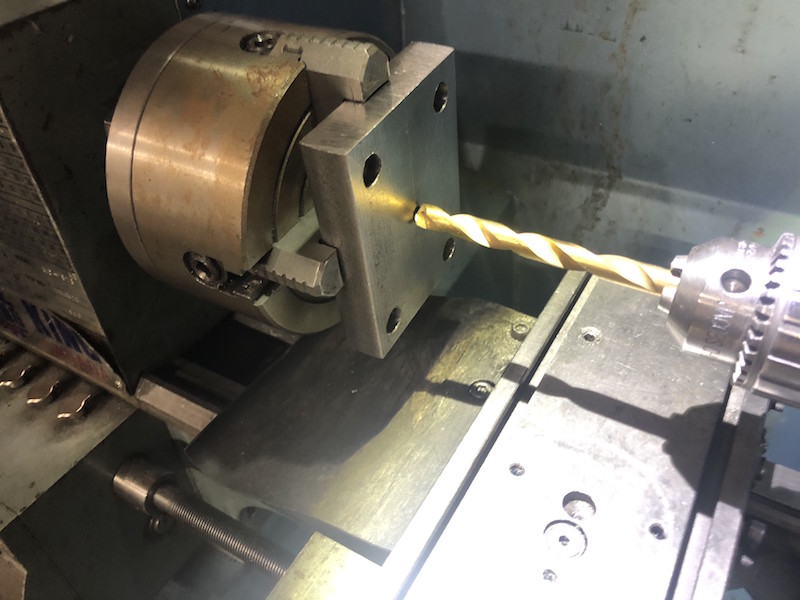
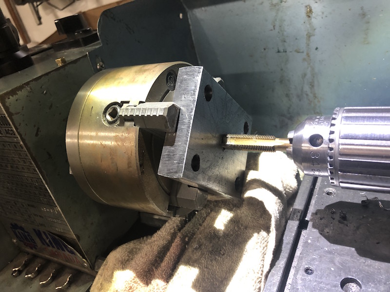
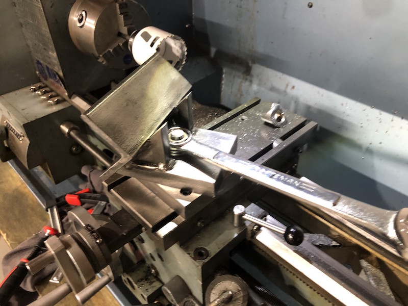
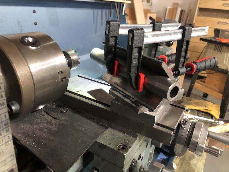
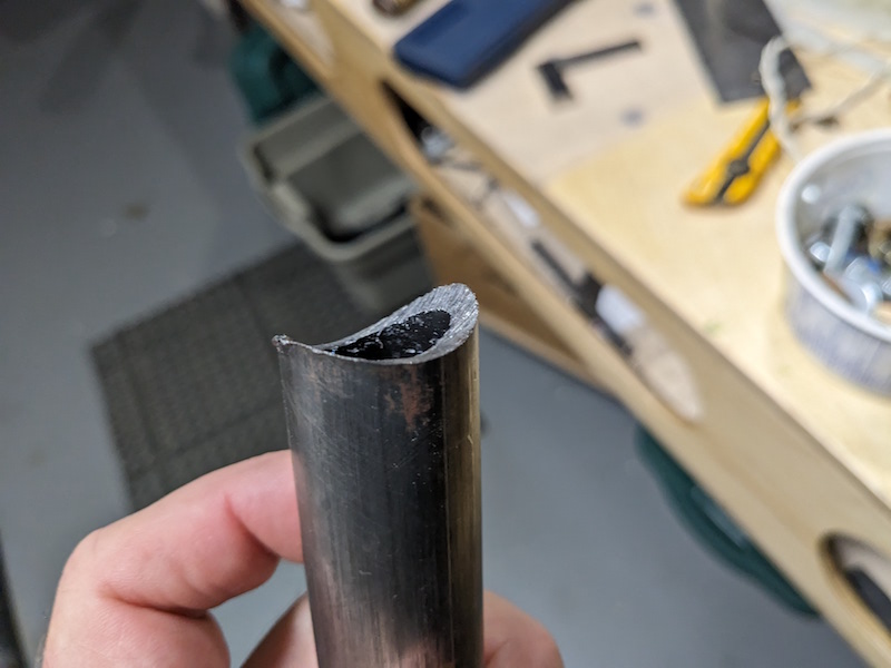
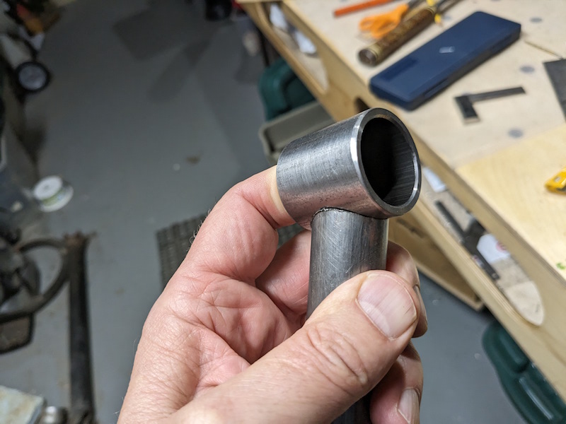
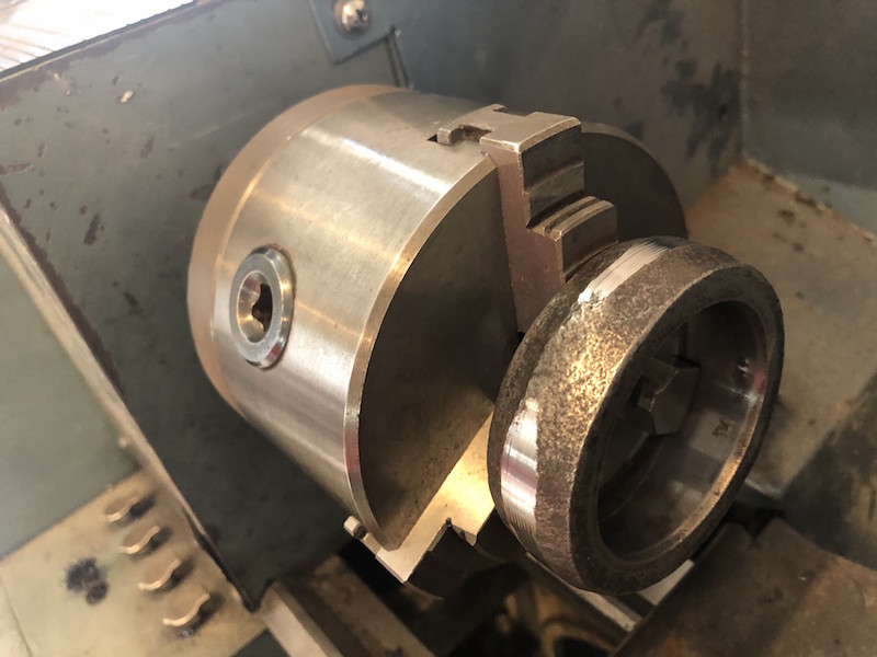
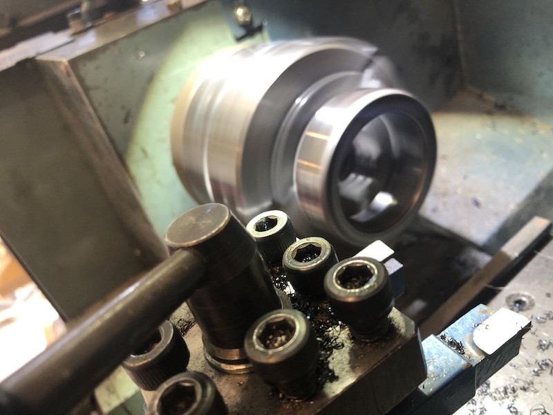
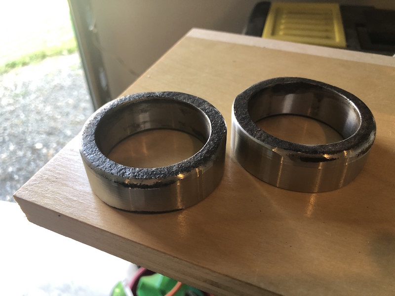
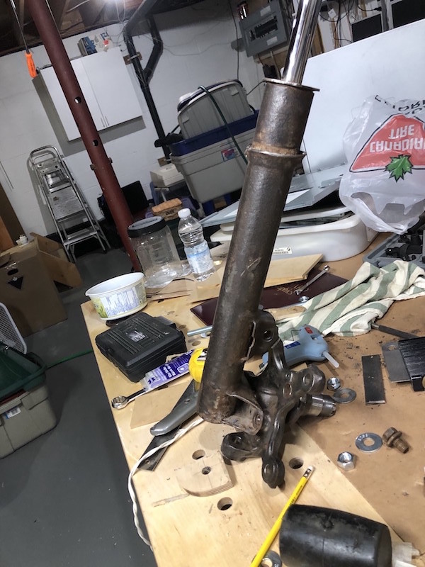
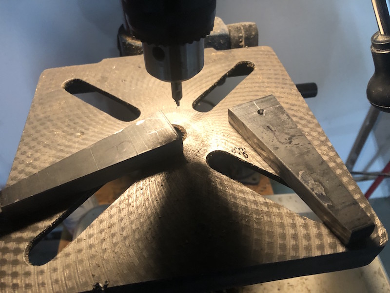
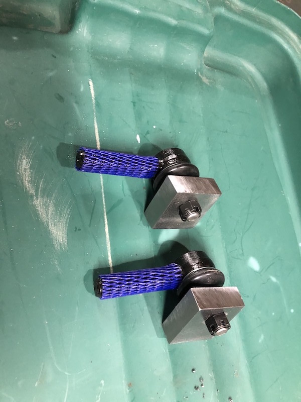
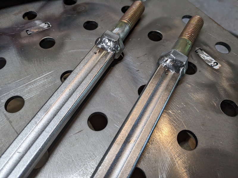
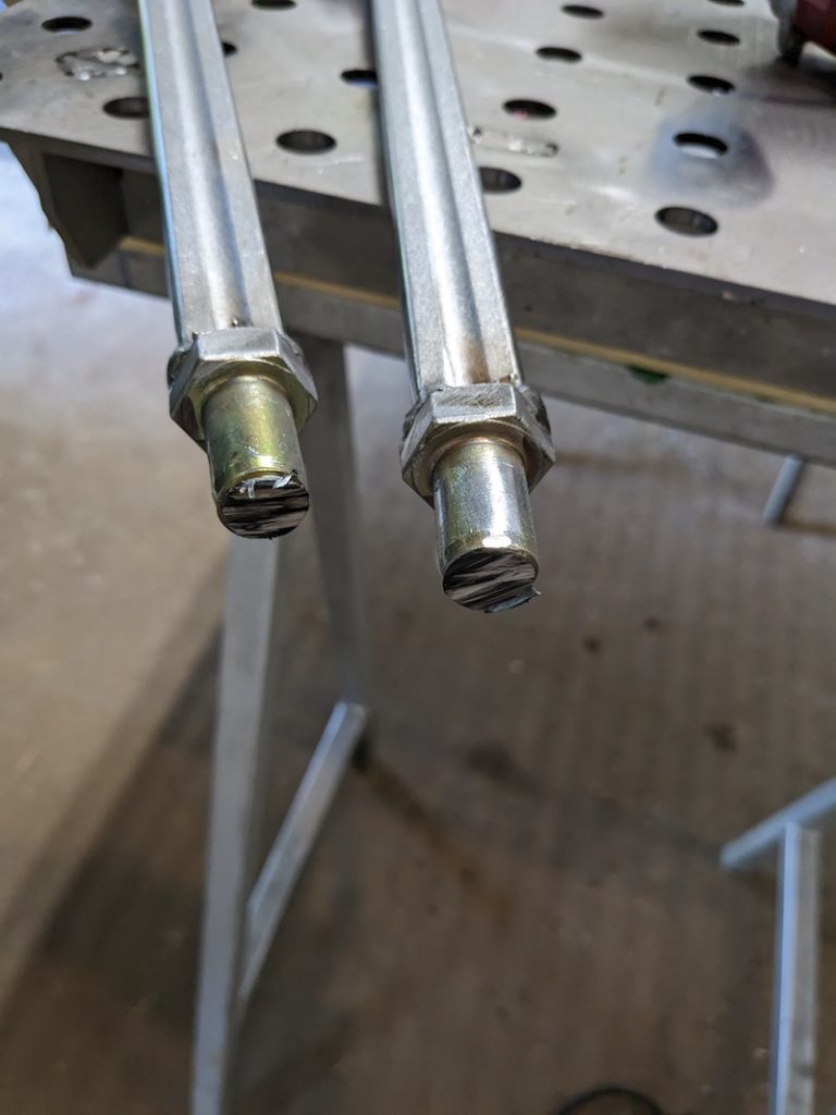
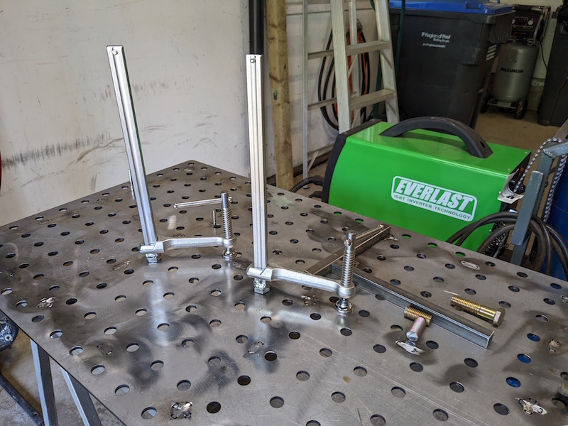
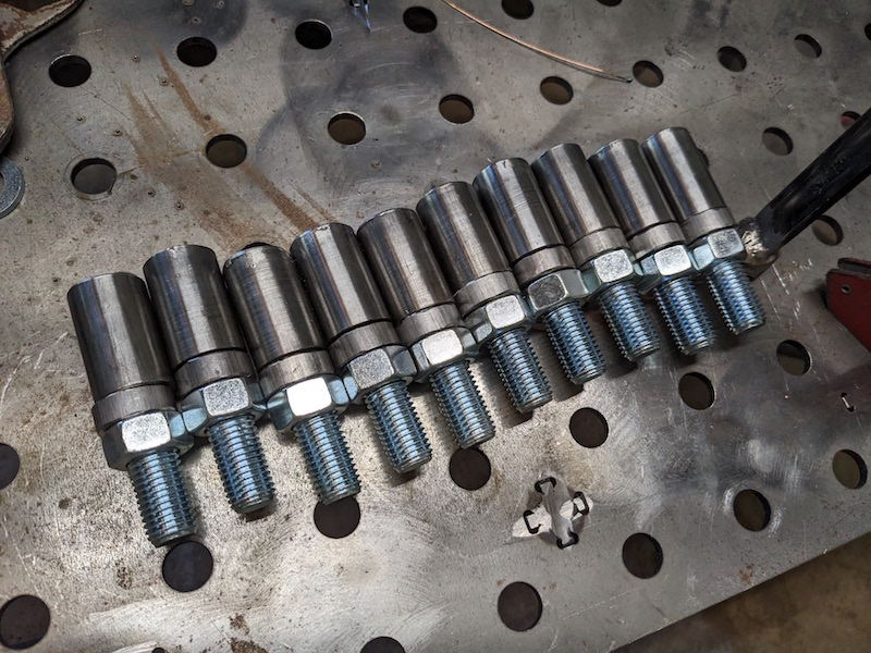
Time to make some posts for the table. I turned the heads of some 3/4″ bolts so they fit inside a bit of leftover 1″ DOM tubing. I then welded the tops and touched up the posts with the angle grinder.

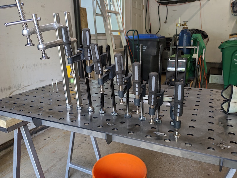
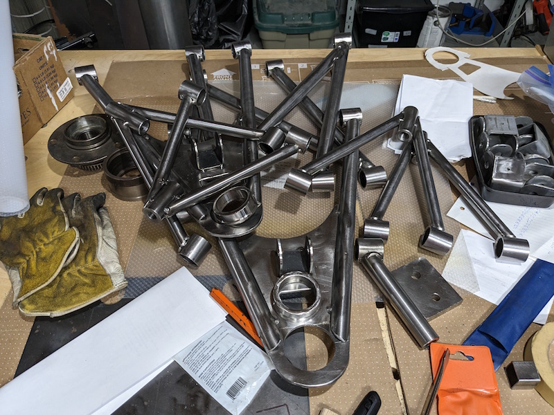
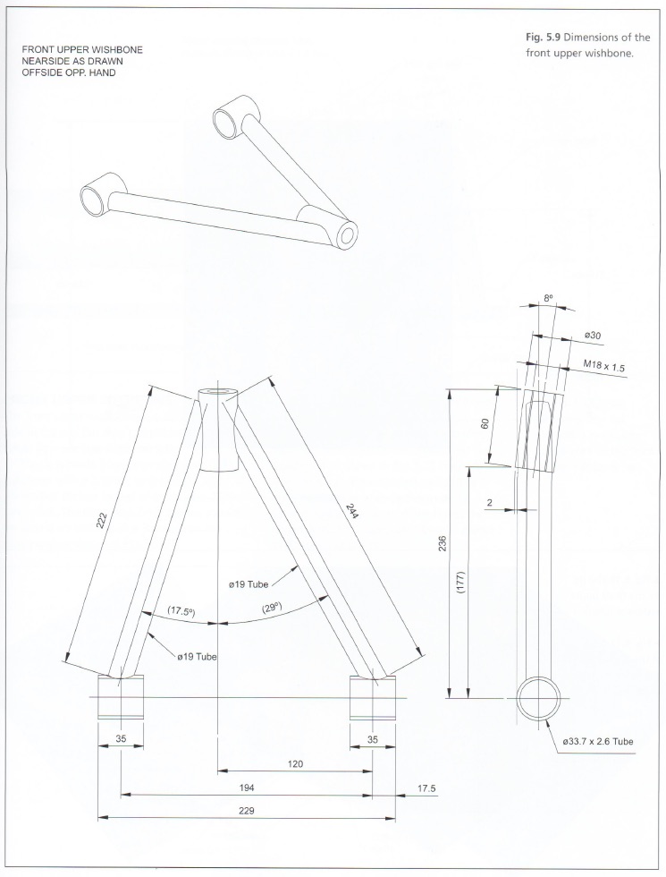
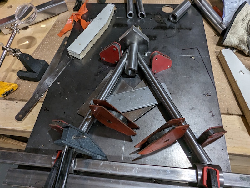
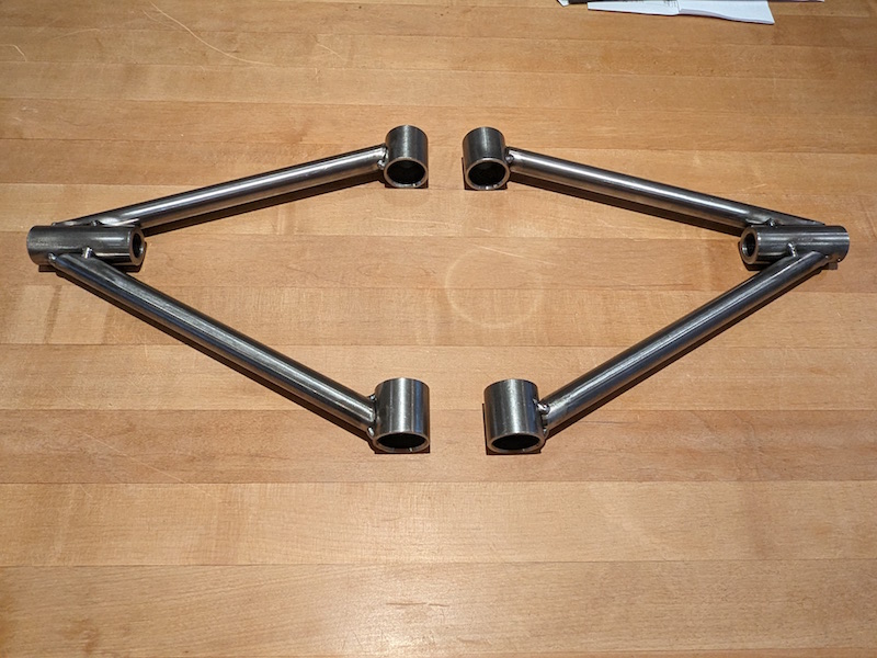
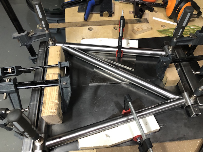
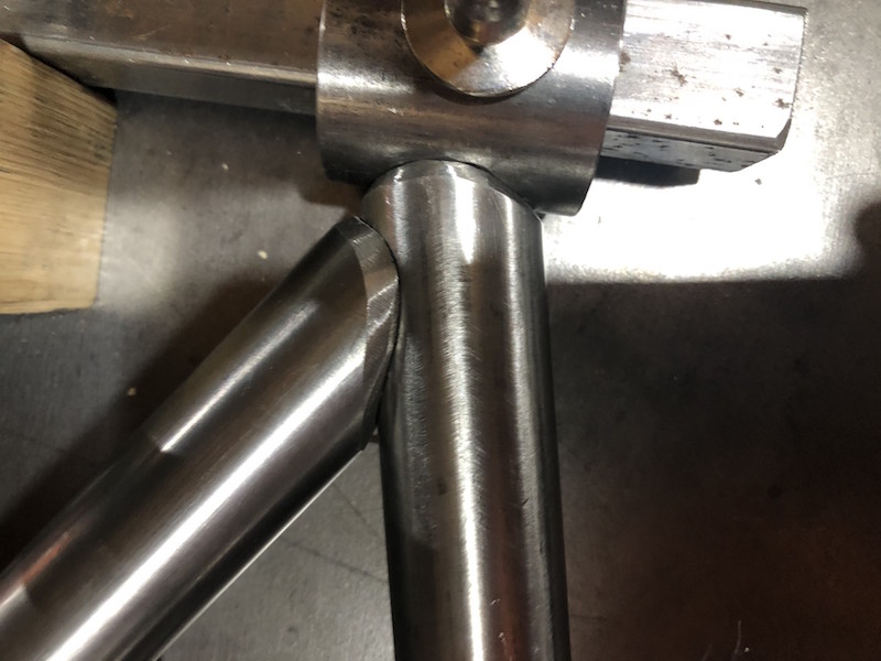
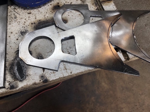
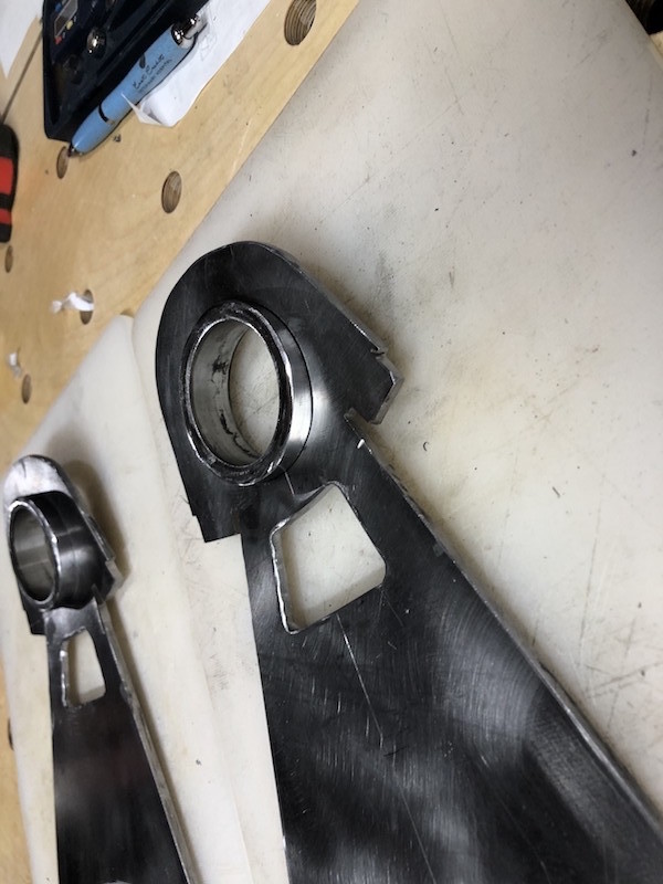
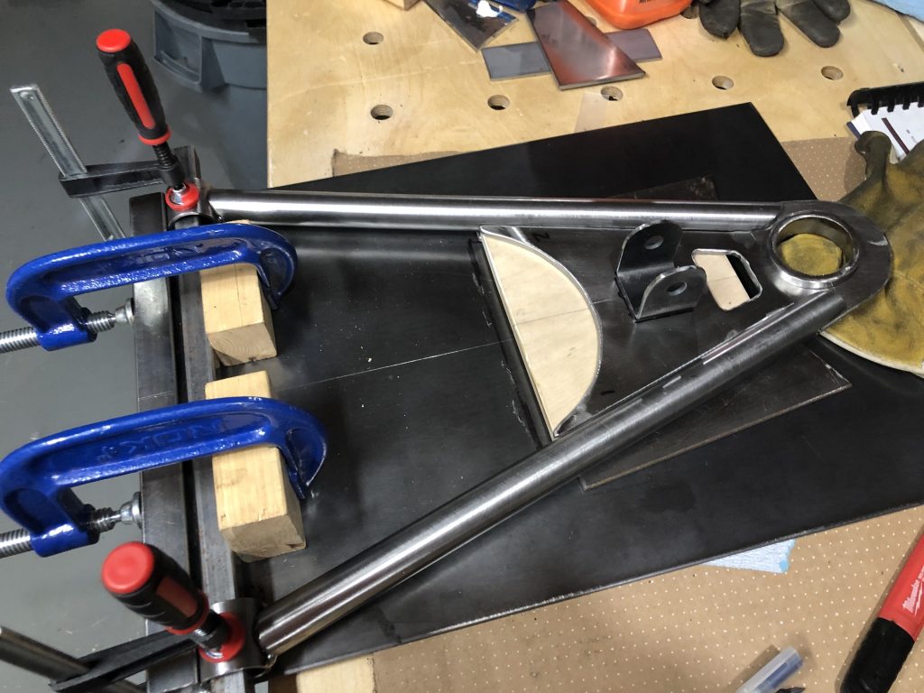
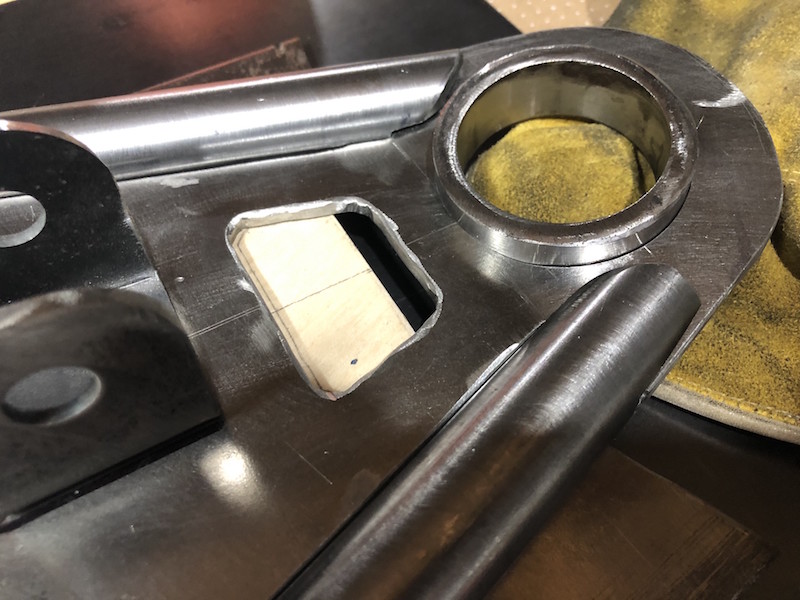
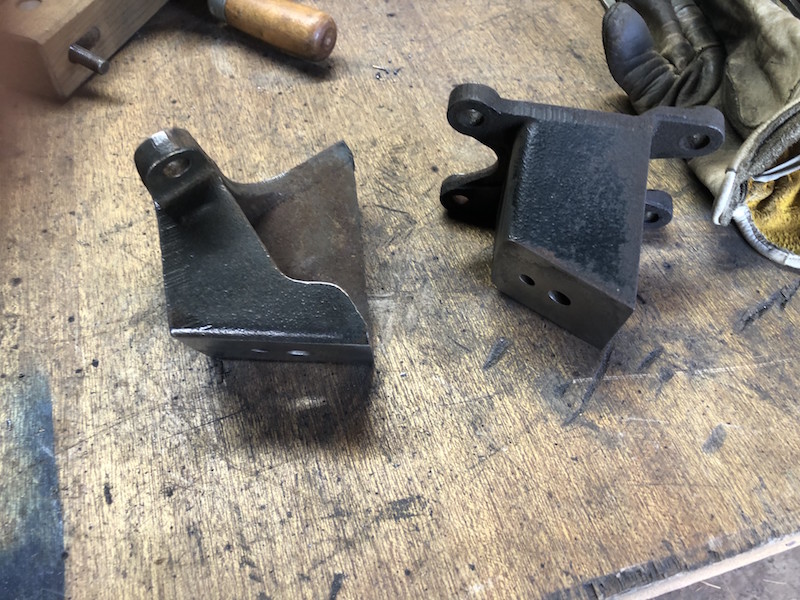
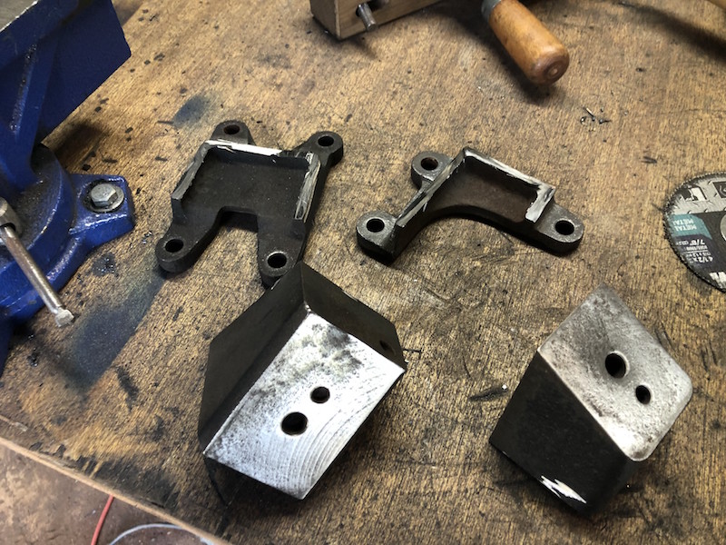
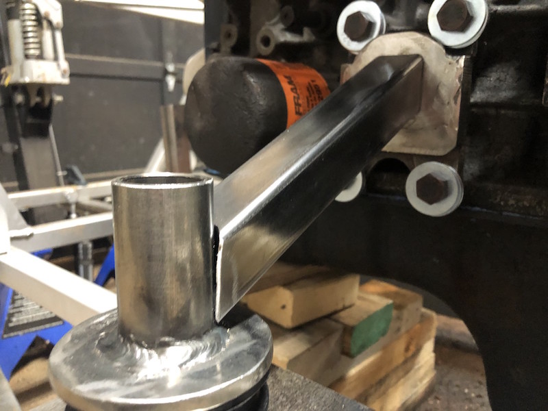
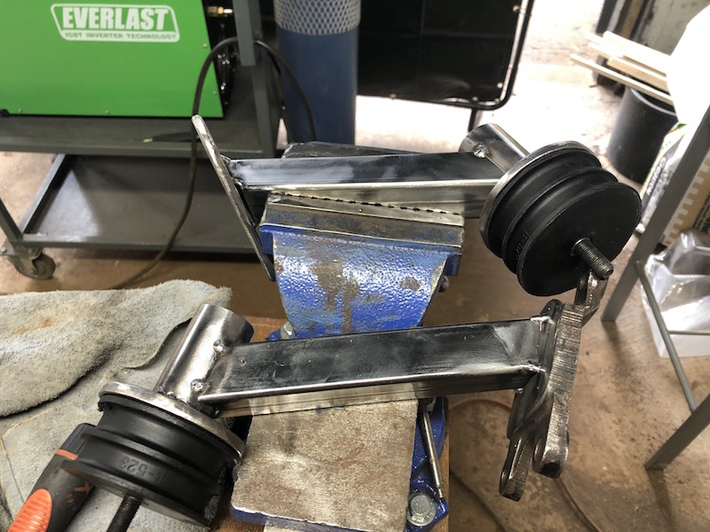
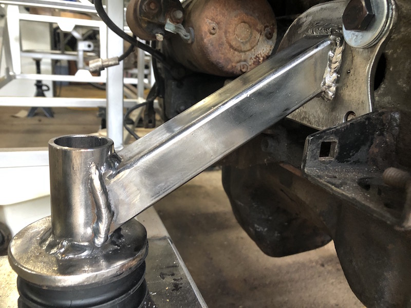
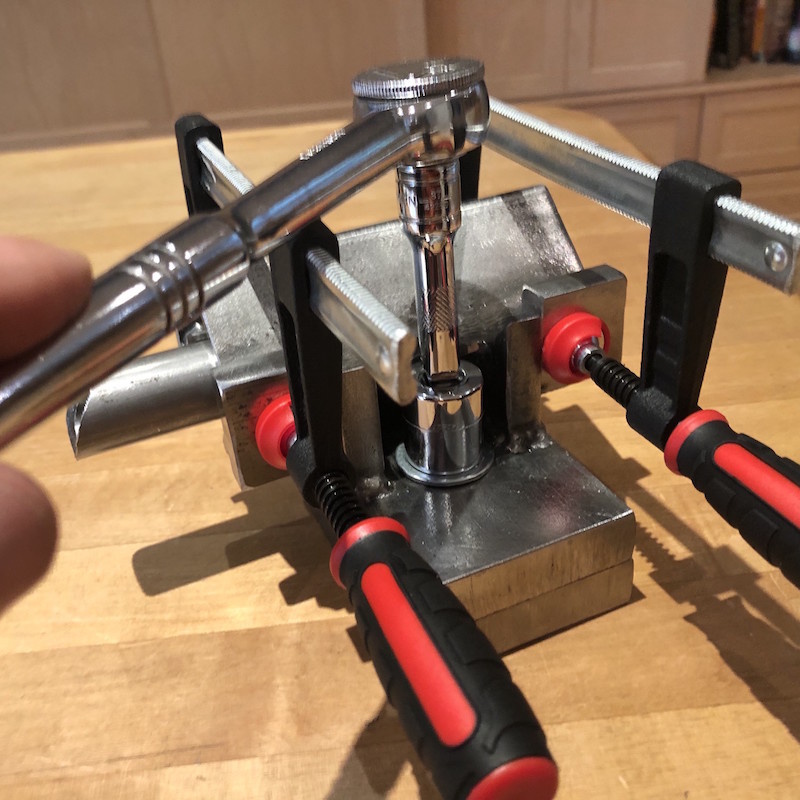
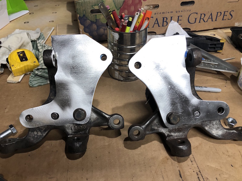
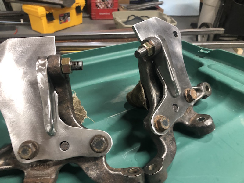
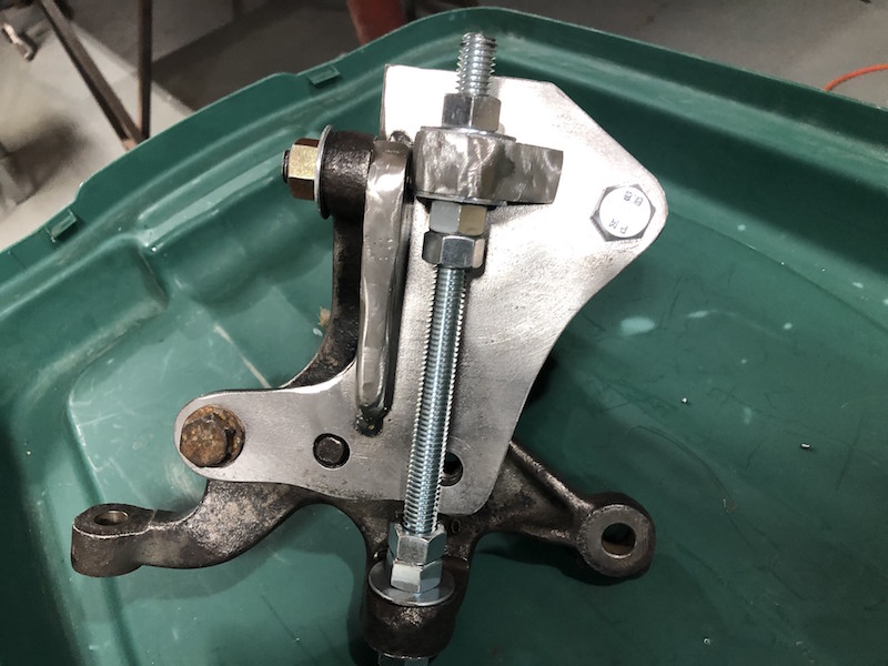
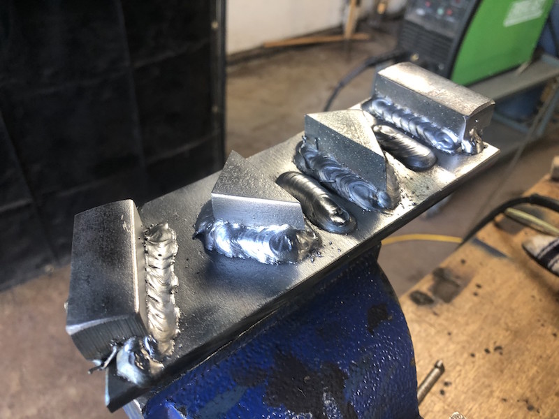
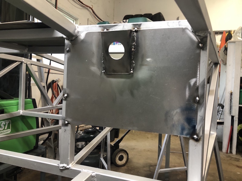
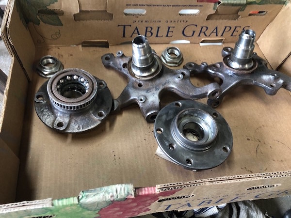
Now I have plenty of tools for the table, time to use them on all the control arms that have been waiting to get fully welded.

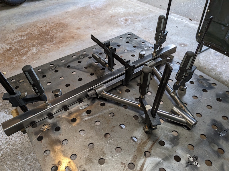
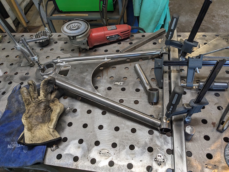
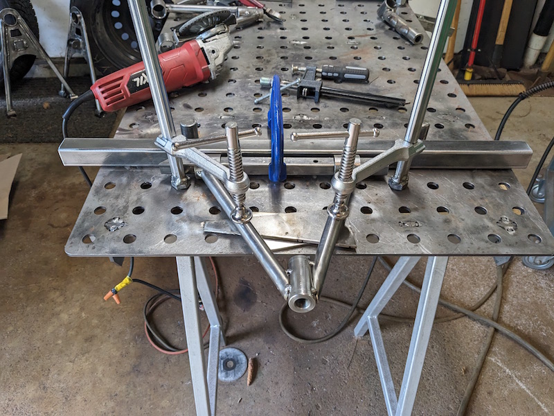
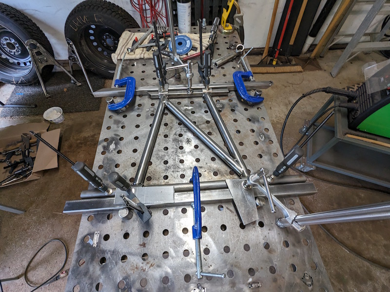
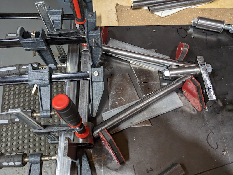
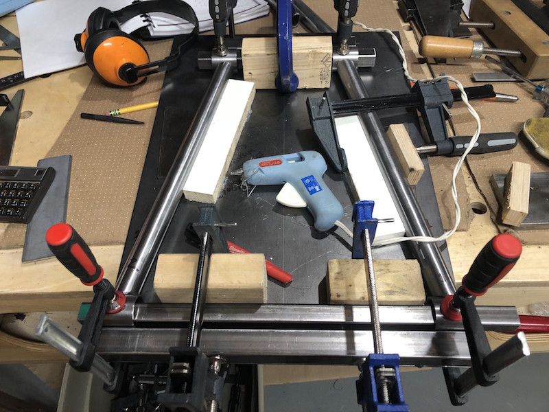
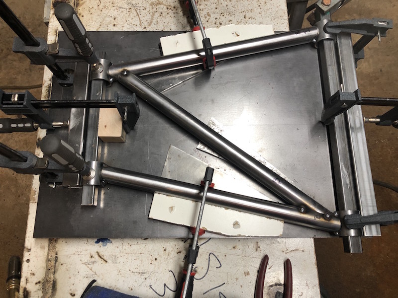
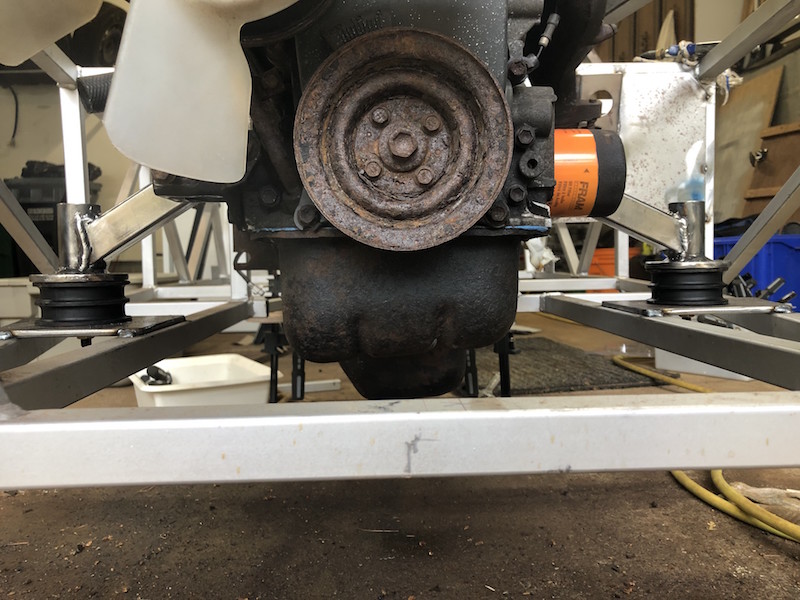
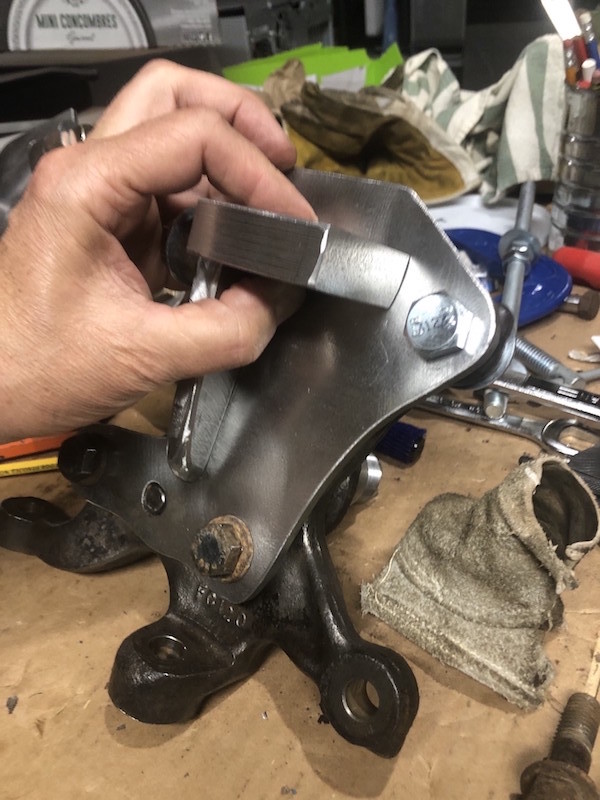
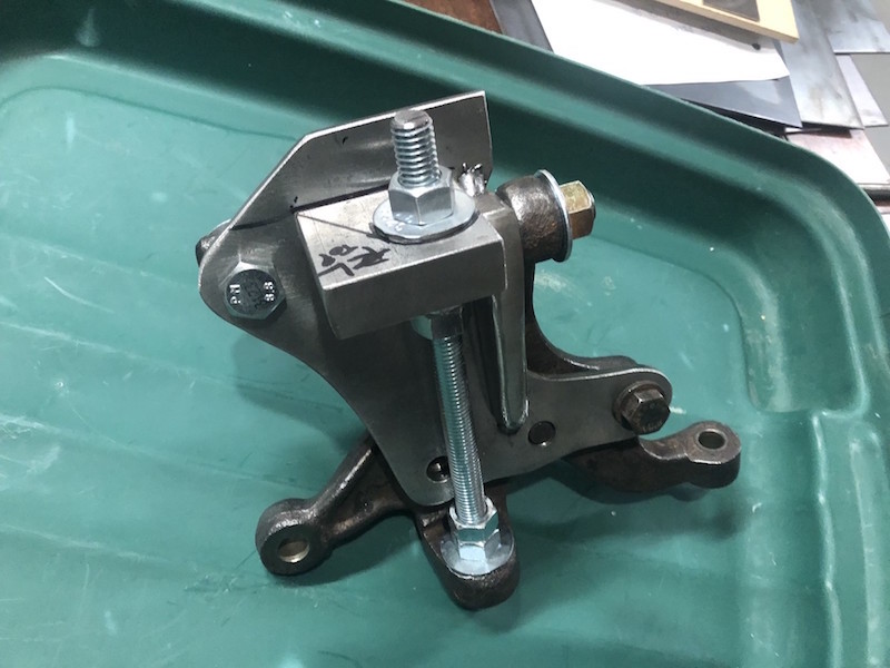
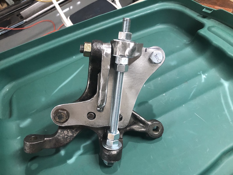
Using all of those new tools to secure the control arms for welding.
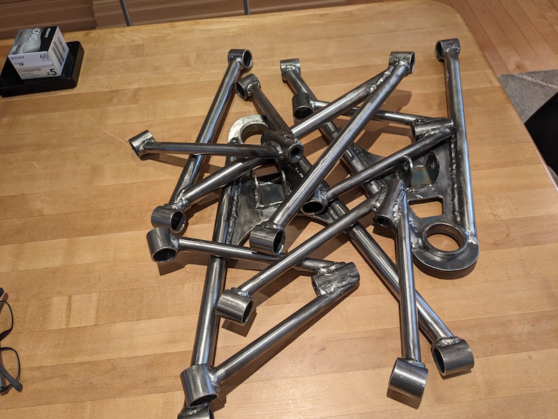
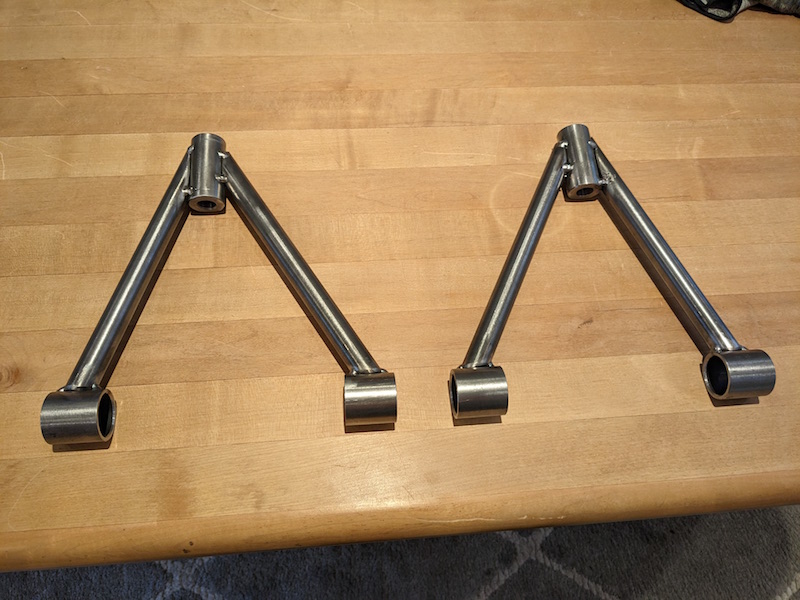
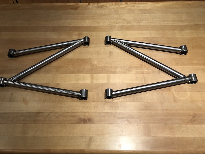
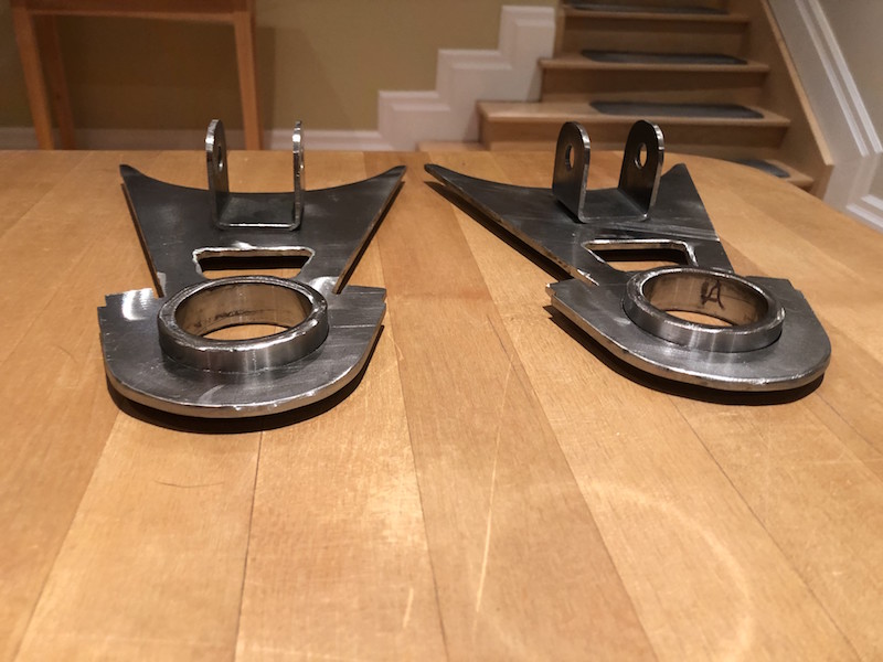
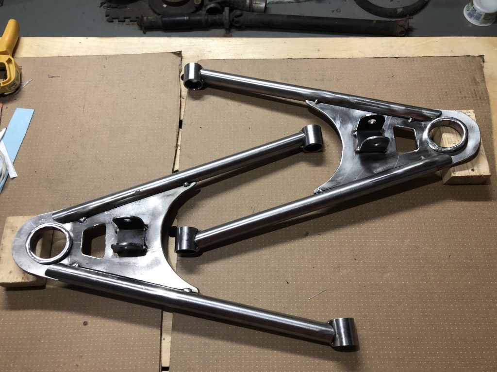
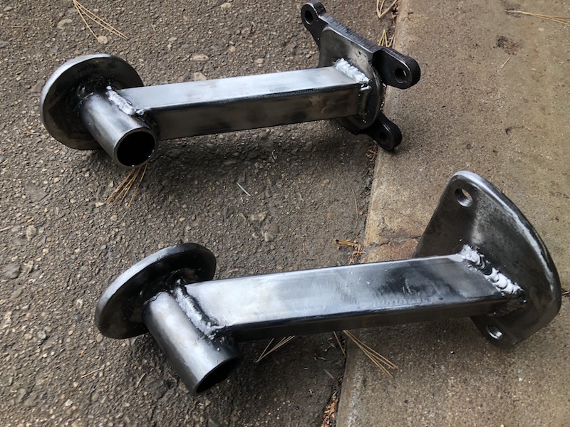
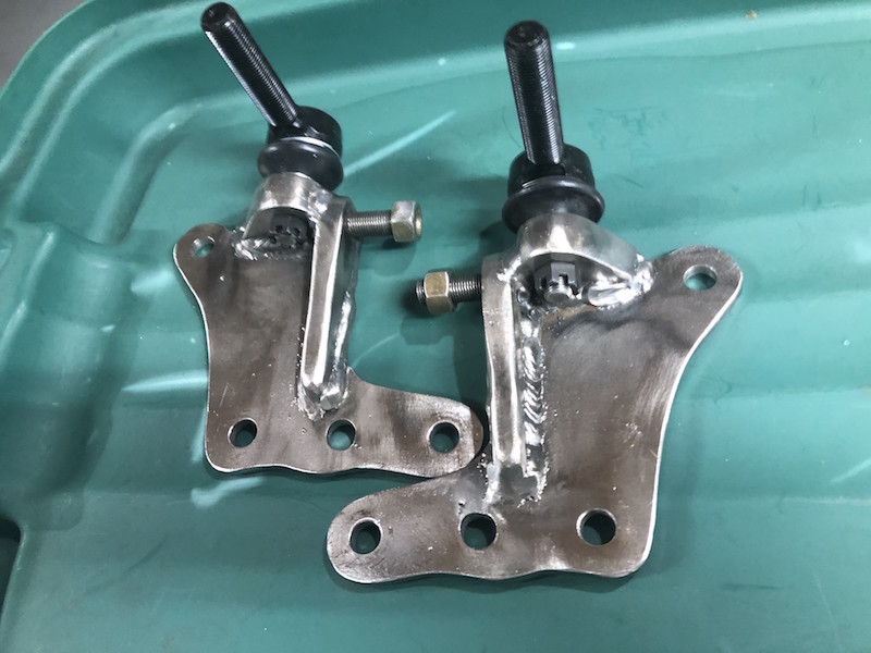
Done!

Loading

039 Bushings by the Bushel (March 2023)

Time to make bushings for all of those control arms.

Here are the bushings required for the car, they are split so two are required for each bushing tube. Here are all the control arms with bushing tubes attached, we are going to need a lot of bushings!

The book calls for Polyurethane material but it is difficult to machine at the hardness required. Polyurethane could be mixed in liquid form and pored into bushing shaped molds but since I don’t have any molds we will be substituting. Delrin is a harder plastic that is easier to machine, it’s self lubricating and is available as round rod. That’s what I’ll be using.

I started by cutting the rod into pieces using a radial arm saw. Each piece is long enough to make 2 bushings. I then center drilled them and faced the ends in the lathe.

Next I used a parting tool to to cut the relief that defines the shoulder of one bushing and turned that end down to size.

Now I could flip each blank around use the parting tool to define the other bushing shoulder and turn the end other down.

The parting tool marks the cutoff point for the 2 bushing halves but before splitting them I beveled the corners to make it easier to press them into the bushing tubes. There you have it a bushel of bushings.

Loading

038 Suspension part IV (February 2023)

In the tradition of saving the worst till last, I give you the front upper control arms.

The issue with these control arms is that the threaded tube that holds the upper ball joint is offset 8 degrees. I will need to do some “innovative lathe work” as my tube notching attachment is designed to make notches that have zero degrees offset. This design also means that we need a more complicated jig as the left and right hand pieces are unique cannot be flopped from side to side (because of the offset).

This jig is similar to the one used for the rear upper control arms with a couple exceptions. We are using 1/2″ plate and need to cut 8 degrees off the edge of the upright so that the threaded ball joint holders are not held horizontal for assembly. Instead of making two jigs (right and left) we can use one with 2 positions for the threaded ball joint holder. Finally, we trim the plate to length.

Here is the single jig that can locate a ball joint holder in one of 2 positions at the required 8 degrees off the horizontal. Now, how to cut the 3/4″ tubes to connect to it?

My solution was to cut a wedge to use in the tube notcher to create the offset. The wedge is not 8 degrees because the angle iron faces are at 45 degrees so some trigonometry was used to come up with the right angle (11.3 degrees I think). The right image shows how the wedge is used and the precarious job of clamping the tube in place.

Cutting is very slow going and again the cut bottoms out in the hole saw and needs to be cleared before finishing. The results are good but the process is a bit scary.

Now we can use the jig to set up each of the control arms and tack weld them. That is a lot of work for 8 degrees!

Loading

037 Suspension part III (February 2023)

Next up, the upper rear control arms.

Each of the four control arms present different “learning opportunities”. These arms are not symmetrical, but they are flat so one jig can be used to create both the left and right parts. They just need to be flipped to orient them properly on either side. They also use a heavy threaded holder at the pointy end. A small fabricated assembly (threaded rod and bushing holder) threads into it and allowing camber adjustment of the rear wheels.

I started by making the heavy threaded holders for both these and the front upper control arms. About this time I realized I could not build this car without a lathe! The solid stock spins in the chuck and a drill bit on the tail stock (Jacobs chuck) is advanced into the work piece. The hole is drilled progressively starting with a center drill to establish the center and then working up to the the hole diameter required. Liberal amounts of cutting oil are brushed onto the bit to help cool it and aid in cutting.

The lathe is also used to cut the thread in the hole. A crescent wrench was used to turn the chuck slipping onto the jaws of the 3 jaw chuck. This is slow work!

The front and rear threaded holders finished. The front pair are on the left.

Another jig needs to be made up with a base tube to clamp the bushing tubes in position and a vertical plate (with a hole) to support the threaded holder. The holder can be bolted onto the vertical plate (made out of a random shape piece of steel if you are curious) to hold it solidly in position.

Tubes were prepped, notched and touched up before getting a good fit. I used several welding magnets to hold the tubes in position for tacking. Again, scrap plate was used to support the tubes at the appropriate height.

Voila!

Loading

036 Suspension part deux (January 2023)

Next on the hit list are the lower control arms for the back end.

Hey these look pretty complicated too! Some funny intersecting angles and lots of notching required.

Again we use a jig to ensure that everything gets lined up properly. Here I have the 4 bushing tubes clamped in place, now I just need to make the zig-zaggy tubes.

The first order of business is to notch all the outer tubes. They have bushing tubes on both ends and are pretty straight forward to notch.

I hot glued a couple particle core strips down to align the outer tubes.

Both ends of the are fitting nicely. I’m using scrap 3/16″ plate to space the tube up off the jig as it is smaller diameter than the bushing tubes.

Cutting the acute angles for the cross brace was challenging. The cut was so long that the waste piece inside the hole saw was bottoming out. I had to back the tube out, cut off the waste piece with the angle grinder, and reengage the work piece to finish the cut. The results were very good.

I relocated the particle core guides to the outside of the tubes because they were interfering with the diagonal brace (of course). Things are fitting very well!

A trip to the welding shop and everything is tacked together. I will wait till I have all of the control arms tacked together before fully welding them. I need more time to get my nerve up LOL.

Loading

035 Suspension of disbelief (December 2022)

As in I can’t believe how much work this is!

Part I – Lower Front Control Arms

I am starting with the lower front control arms. These are arguably the most complex of all the control arms but they do have the simplest tube to tube joints (only the bushing tubes) and since I am new to tube notching I decided to start with them.

The doner car from the book uses a bolt in ball joint while the BMW has a pressed in ball joint. I have modified the web plate lengthening the nose of to accommodate the holders that were machined on the New Brunswick trip. The center of the ball joint remains the same as the drawing above. I used a paper template to trace out the shape on the steel plate.

Step one was to drill the holes for the ball joint holders. I used a a hole saw that was slightly smaller than the outside diameter of the ball joint holder.

I then used the lathe to turn down the holders leaving a small shoulder that would help position the holder height in the web plate.

After much cutting and grinding the plates are done. I named my angle grinder CNC.

The plates required a 10 degree bend on the head end, that was achieved with the hydraulic press.

Time to notch some tubes to go with those web plates. By cutting a double length piece in the center I get two identical notches and cut my work in half. Win Win!

After notching any burrs get cleaned up and the edge of the notch gets beveled on a belt sander, this will create a better connection when welded.

The 4 tubes for the front lower control arms beveled and ready for the bushing tubes. I also cleaned the inside of the tubes using some acetone and a cleaning “rod” powered by my drill. This got rid of any metal particles in the tube and hopefully any oil or contaminants from the manufacturing process. Contaminants inside the tube could affect the quality of the weld.

I tack welded the bushing tubes onto the notches and then split the other end of the tubes. I had decided to extend the tubes beyond the tongue that was left on the web plate and the tubes needed to be pass over the top and bottom of the plate.

A jig is used to align all the parts so that they can be tacked together. Here you can see the fit of the extended tubes (compared to the opening drawing) and the detail of the split end.

A chilly trip to the garage and the lower control arms are tack welded.

Loading

034 Everything is a process (October 2022)

Time to start on the suspension control arms. Before we get too far into it we are going to need to make a bunch of bushing tubes as they are common to all the control arms. These short tubes are welded to the ends of the control arms, have bushings pressed into them and provide the pivot points for the suspension arms to swing.

Lengths of 1-3/8″ DOM tubing (1/8″ thick wall) are cleaned using the lathe and a brillo pad. It is a lot easier and less work to clean the whole tube than try to clean the individual bits later.

The chop saw is used to cut the tubes to length (about 1-3/8″ long), it does a good job but a bit of a clean up is required.

A flapper disk removes the large burs and then I used the lathe to lightly face the tubes and and make a small bevel to the inside edge of each piece.

After and before.

That’s a good days work.

Loading

033 Mount up and ride (October 2022)

Before the car frame gets hung up for the year we will be making motor mounts for the Suzuki engine.

These are the cast steel motor mounts that came out of the Suzuki Samurai. While they won’t fit the new frame parts of them may be useful. I use the 4 hole casting as one mounting plate and will make a simple plate for the other.

Used the engine hoist to put the motor in the frame, then leveled it and blocked it in position.

I made the mounting plate for one side of the motor and added a filler piece to the cast mount I was reusing.

I ordered rubber motor mounts from an old Land Rover model because they were simple. I made round top plates for them and welded on upright tubes. I cut some flat plate and drilled it to act as the base for the motor mounts on the car frame.

Here is the basic set up on one side. The base plate will be trimmed to match the frame members that it covers and a piece of square tubing needs to span between the mount tube and the mounting plate on the engine. The square tube will need to be notched at one end (to fit the profile of the round tube) and cut at an angle on the other to mate up with the mounting plate.

The first attempt at tube notching for production! The angle between the drill bit and tube holder is set with a Digital Angle Ruler. Then the hole saw is mounted, the tubing is clamped in position and the cutting commences. Hole saws are very coarse and so great caution and patience is needed to make a good cut.

All goes well and the square tubing fits nicely.

Both mounts tacked and ready to be fully welded.

Fully welded and cooling.

Actually holding up the engine!

Loading

032 Notch up another 0ne (October 2022)

Soon it will be time to start work on the suspension components. The control arms for the car (front, back, upper and lower) are all fabricated using DOM (Drawn Over Mandrill) round tubing.

Here is the lower rear control arm geometry. It’s made up of 3 – 1″ diameter tubes that connect as well as 4 short bushing tubes. The bushing tubes provide attachment points to the frame of the car and the rear hub. How are we gonna make these?

We can’t weld a square cut tube onto a round tube, the gaps are too large and we wouldn’t get a strong joint. The solution is to notch the tubes so that the profile matches the shape of the tube being connected to. I saw “a guy on YouTube” using his lathe to do this so that’s the route I’m taking. A hole saw is driven by the lathe chuck and a sturdy fixture is attached to the lathe’s cross slide to position and hold the tube for cutting. First I need to make the tube holder.

I started with 1/2″ plate to make a base that will attach to the cross slide of the lathe using t-nuts, just like the tool holder does.

Next, I used the 4 jaw chuck, centered the rectangular base plate and drilled a center hole. I then threaded the hole while it is still on the lathe. Tapping is done by hand, manually rotating the work piece into the tap slowly just as you would with a tap handle but the lathe maintains perfect alignment and makes it easier.

Time to make the upper holder plate. Once again 1/2″ plate is used, the end is beveled to 45 degrees and extended with a triangular piece of plate on each side. A length of heavy angle iron is attached to the triangles and base. The angle iron is horizontal with the center line of the angle at the same height as the center line of the lathe chuck. A 1/2″ stud is attached to the bottom plate and passes through the upper holder allowing it to rotate and be locked down at any angle.

With the basic parts finished it’s time to test. The holder is mounted on the cross slide and the desired angle is set and locked. A hole saw of appropriate diameter is mounted in the lathe chuck and a piece of tubing is clamped in the holder. I use the lathe travel to manually feed the tubing into the hole saw and make the cut.

The end result is a very tight fit between the tubes.

Here are the completed components, clamping tabs were added to the top plate, a front clamping bar was made to make attaching round tube more secure and enough relief was created to allow a ratchet to be used for angle locking. This geometry means that any diameter of tube clamped in the holder will be centered on the hole saw without any adjustment needed.

Loading

031 On the road again (September 2022)

The end of summer is marked by the annual Boyz Camp-O-Ree. 2022 was a milestone event – celebrating 30 years of “camping like it’s 1991”! Tom came in from New Brunswick and the plan was for Paul and I to drive back with him, check out their new homestead and do some machining on his lathe.

All the usual suspects were at Camp-O-Ree and the event included a static t-shirt display entitled “Camping through the years”. A good time was had by all. Before hitting the road I needed to do some pre-work.

These are the ends of the BMW front control arms that were cut off before the car was sent to the scrapyard. The plan is to reuse them in the new Locost control arms. They are part of a heavy steel casting and need to be trimmed and turned on a lathe to get them ready.

Trimmed with the chop saw, cleaned up with the angle grinder and ready to visit the lathe.

We made it to Nackawic, saw “the” sight and helped do some yard work.

Tom gave me a quick lesson on using the lathe and I was able to clean up the front ball joint holders. I hadn’t operated a lathe since grade 10 shop class and was pretty rusty. Tom insisted that I “borrow” the lathe since he figured I would have a lot of need for it in the next while. Boy was he right! With the lathe loaded in the trunk of the car Paul and I headed back to Toronto.

Thankfully I had the engine hoist to get it out of the trunk. Next problem how to get it into the basement?

Emily didn’t think it was a good idea to just “go for it” and try to hump it down the stairs (smart girl). I made a ramp and it slid down very easily with everyone supervising.

Here it is, happy in it’s new home!

Loading

030 Arts and Crafts (Summer 2021)

The Lo-cost front suspension uses upper and lower control arms, ball joints and a coil over shock. The BMW doner front end has a lower control arm with ball joint and and a McPherson strut for the upper connection. I need to “design” and fabricate an upper ball joint adapter to replace the strut.

The McPherson strut as it attaches to the BMW hub.

Here is the back side of the front hub with a lower ball joint in place. There are the 3 dedicated mounting points (plus a locating stud circled in yellow) for the strut. The other two mounting points are for the disk brake caliper.

A couple views of the a hub with a threaded rod clamped through the lower ball joint boss. This rod was used as a reference for the location of the upper ball joint.

As a first step, I pieced together a cardboard mock-up of what a ball joint holder may look like.

Next, I made a wooden mock up to see how a solid model with realistic material thicknesses would work. The backing plate and web are 1/4″ thick and the top deck is 1/2″ material. This holder actually bolts on to the hub in 4 places (!) using one of the brake caliper mounting holes as well. The threaded rod and nuts/washers were used to position the top plate.

A couple of views of the wooden mock-up attached to the hub. The top deck attaches to the backing plate at an angle to keep the upper ball joint in line with the lower one. The whole structure is a bit taller than I would like and the bolt that passes through the upper strut attachment boss is awkward to get at. Time for a second iteration.

Here is the Mk II model with a lower height, a bit too low as it turns out. I need to raise it a bit to insure that the suspension arms don’t interfere with the hub during movement. On the right some washers were added to raise the control arm attachment position to check things out.

Here are the Mk I and Mk II mock ups. The Mk II is shorter and will use a stud to attach to the top boss on the hub rather than a bolt. The web is now 1/2″ thick to accommodate the stud. Wooden models are a great way to develop a complicated part. Wood is quick to cut, easy to shape, and fast to assemble using a hot glue gun.

No CNC cutting here! 1/4″ thick backing plates are drilled for the bottom 3 holes and ready for cutting with the angle grinder.

Rough cut and fitting on the hub.

Lots of consumables later….

The backing plates fitted on the front hubs. They were ground to the final shape using flapper disks and a surfacing disk got rid of the mill scale. Some trimming is still required on the top but we need the web and top plate fitted first.

1/2″ plate was cut, drilled and tapped for the web.

The webs were ground to their final shape and 1/2″ studs installed. Here the back plate is attached to the hubs and the web bolted onto the upper boss.

Creating the top plate was more of a challenge. They are going to be 3/4″ thick to provide a suitable depth for the ball joint taper. The chop saw cut the 3/4″ plate to the correct angle to meet the back plate. That saw is amazing!

The top plate hole position was carefully measured, marked and drilled. Now the threaded rod, nuts and washers can be used to set the position of the top plate. The top plate is marked to be trimmed to the final shape.

A tapered ream was used to open up the hole in order to match the taper on the ball joints.

With the top plate cut and ground to shape I could determine exactly where to trim the top of the backing plate.

A few practice welds on some heavy plate and the ball joint adapters get fully welded.

The finished product is pretty compact and looks massively strong. In the Lo-cost design the upper control arm is not constrained, the coil over shock attaches to the lower control arm. This means that the lower ball joints carry the weight of the car and the upper ball joints see much less load.

The progression from origami to finished component!

Loading

029 Let’s do the time warp! (Spring 2022)

I’m Back!

Okay, I did promise to keep on top of the blog when I last posted two years ago (December 2021 yikes!). In my defense, it has been a busy time and car progress has been a bit “spotty” so I never really got into the blog. Sorry about that.. but let’s get on with the story.

The winter of 21/22 came, stayed a while, and went…

and when it did I got to retire – complete with Lo-Cost 7 car cake and custom “G.T.F.O.” license plate!

The car eventually came off the ceiling and work could commence.

Cutting sheet metal for the firewalls.

Tacked in place

Added the driver’s side steering and dash frame.

Time to dismantle and clean up the front hubs.

Fortunately, most of the rusty sheet metal bits are not needed.

Here are the important bits in need of cleanup.

Angle grinders with wire brushes and a pneumatic needle gun do the job.

Loading