Next up, the upper rear control arms.
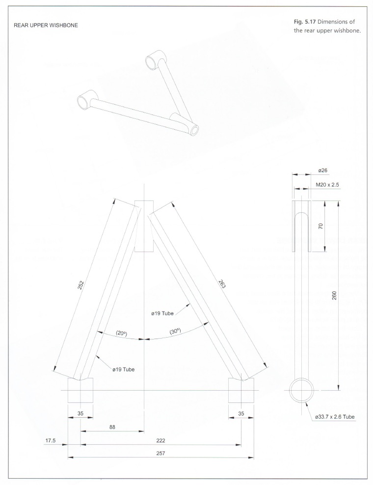
Each of the four control arms present different “learning opportunities”. These arms are not symmetrical, but they are flat so one jig can be used to create both the left and right parts. They just need to be flipped to orient them properly on either side. They also use a heavy threaded holder at the pointy end. A small fabricated assembly (threaded rod and bushing holder) threads into it and allowing camber adjustment of the rear wheels.
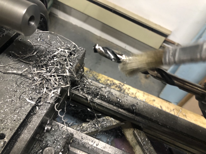
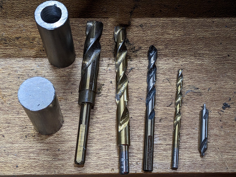
I started by making the heavy threaded holders for both these and the front upper control arms. About this time I realized I could not build this car without a lathe! The solid stock spins in the chuck and a drill bit on the tail stock (Jacobs chuck) is advanced into the work piece. The hole is drilled progressively starting with a center drill to establish the center and then working up to the the hole diameter required. Liberal amounts of cutting oil are brushed onto the bit to help cool it and aid in cutting.
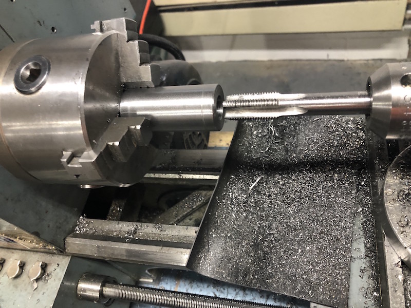
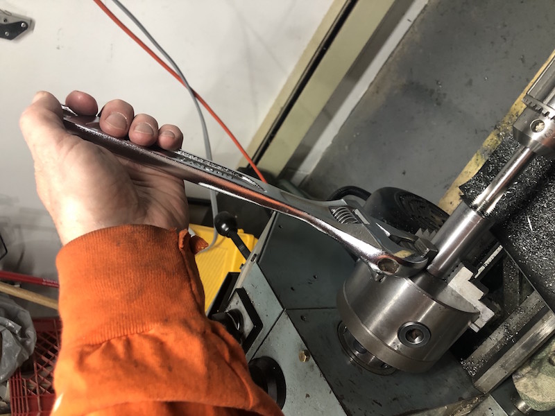
The lathe is also used to cut the thread in the hole. A crescent wrench was used to turn the chuck slipping onto the jaws of the 3 jaw chuck. This is slow work!
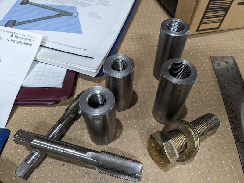
The front and rear threaded holders finished. The front pair are on the left.
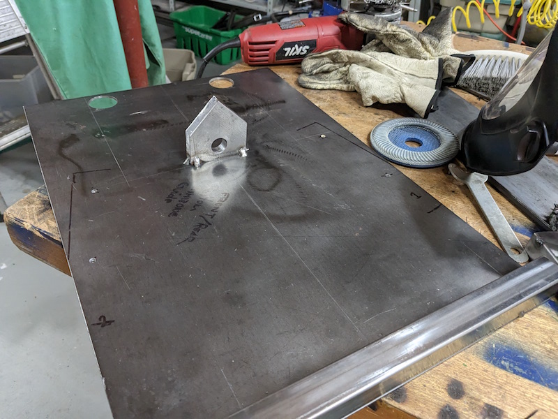
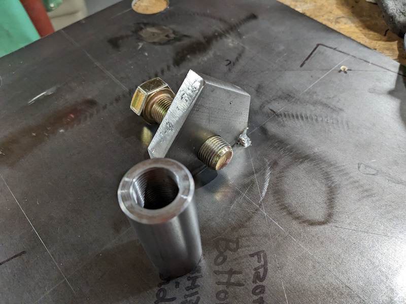
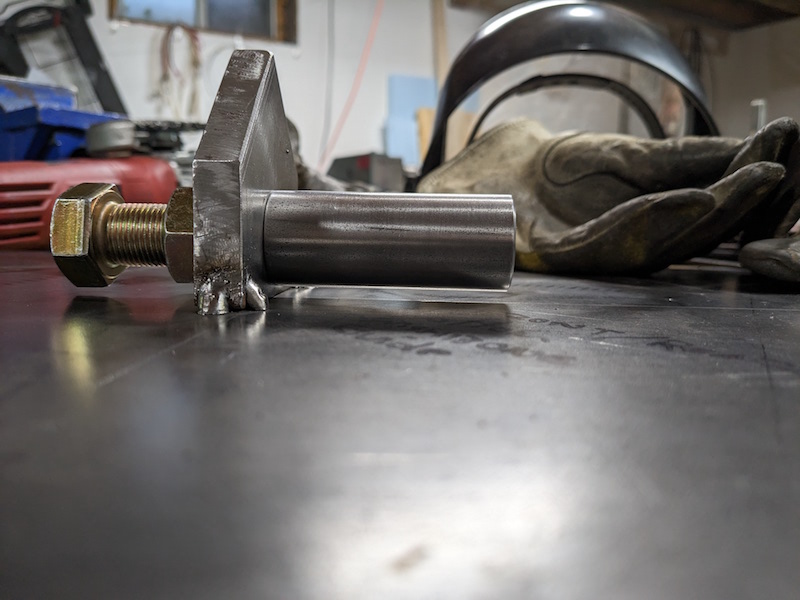
Another jig needs to be made up with a base tube to clamp the bushing tubes in position and a vertical plate (with a hole) to support the threaded holder. The holder can be bolted onto the vertical plate (made out of a random shape piece of steel if you are curious) to hold it solidly in position.
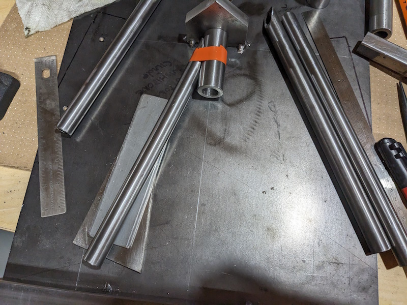
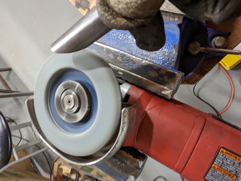
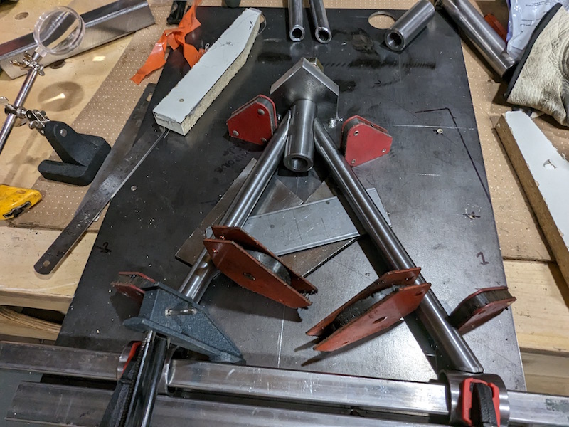
Tubes were prepped, notched and touched up before getting a good fit. I used several welding magnets to hold the tubes in position for tacking. Again, scrap plate was used to support the tubes at the appropriate height.
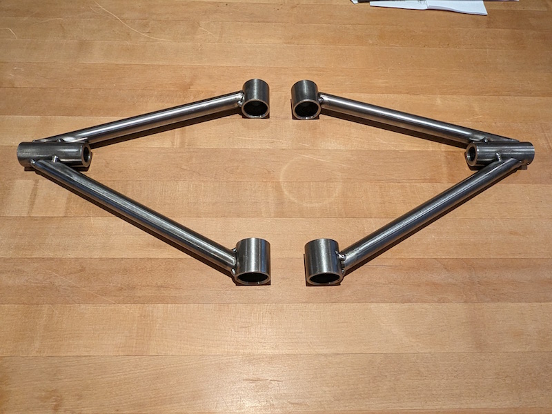
Voila!
![]()