Soon it will be time to start work on the suspension components. The control arms for the car (front, back, upper and lower) are all fabricated using DOM (Drawn Over Mandrill) round tubing.
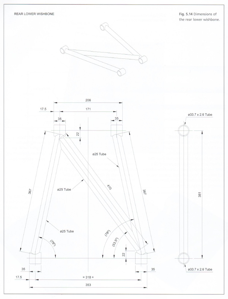
Here is the lower rear control arm geometry. It’s made up of 3 – 1″ diameter tubes that connect as well as 4 short bushing tubes. The bushing tubes provide attachment points to the frame of the car and the rear hub. How are we gonna make these?
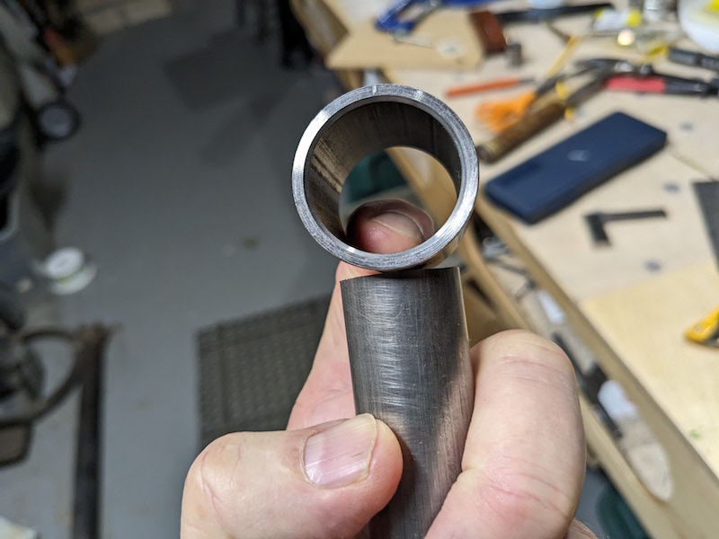
We can’t weld a square cut tube onto a round tube, the gaps are too large and we wouldn’t get a strong joint. The solution is to notch the tubes so that the profile matches the shape of the tube being connected to. I saw “a guy on YouTube” using his lathe to do this so that’s the route I’m taking. A hole saw is driven by the lathe chuck and a sturdy fixture is attached to the lathe’s cross slide to position and hold the tube for cutting. First I need to make the tube holder.
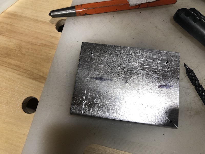
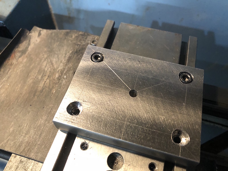
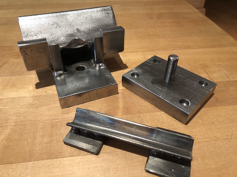
I started with 1/2″ plate to make a base that will attach to the cross slide of the lathe using t-nuts, just like the tool holder does.
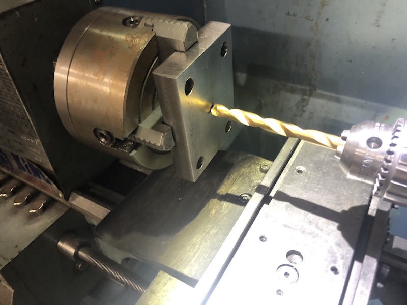
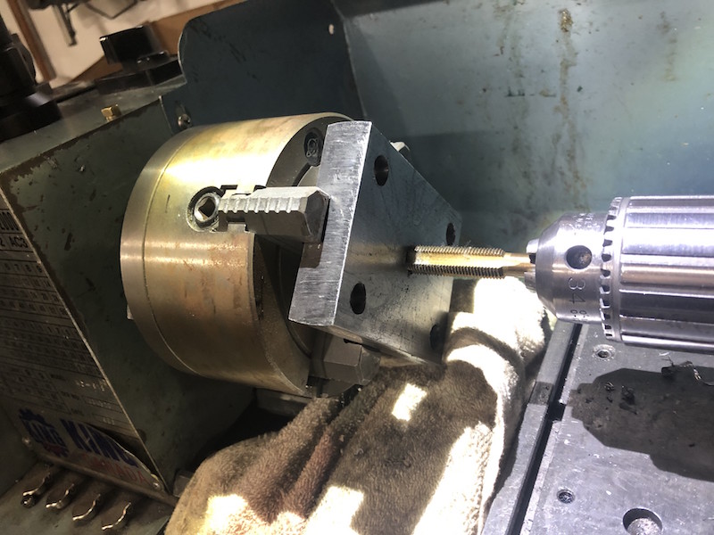
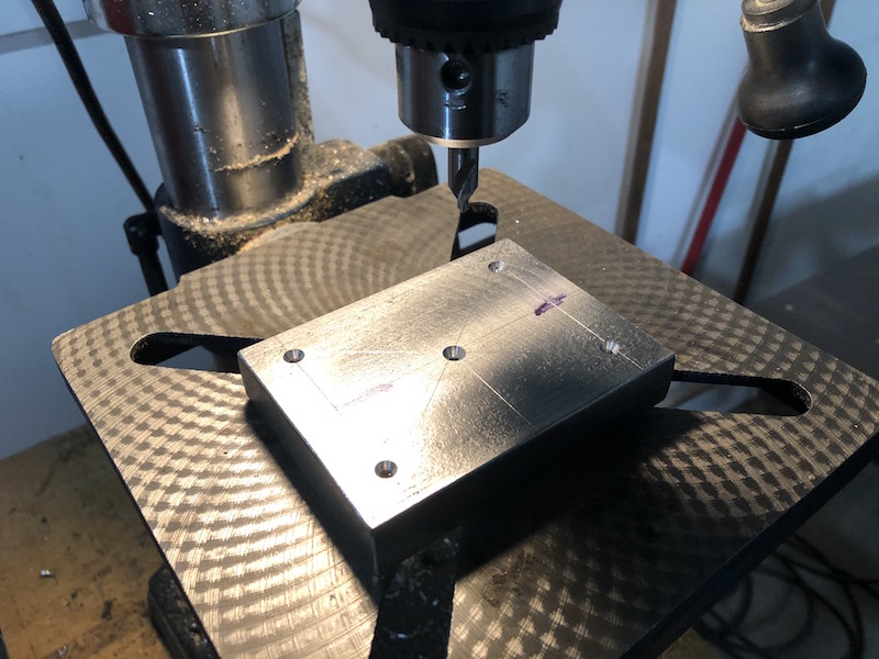
Next, I used the 4 jaw chuck, centered the rectangular base plate and drilled a center hole. I then threaded the hole while it is still on the lathe. Tapping is done by hand, manually rotating the work piece into the tap slowly just as you would with a tap handle but the lathe maintains perfect alignment and makes it easier.
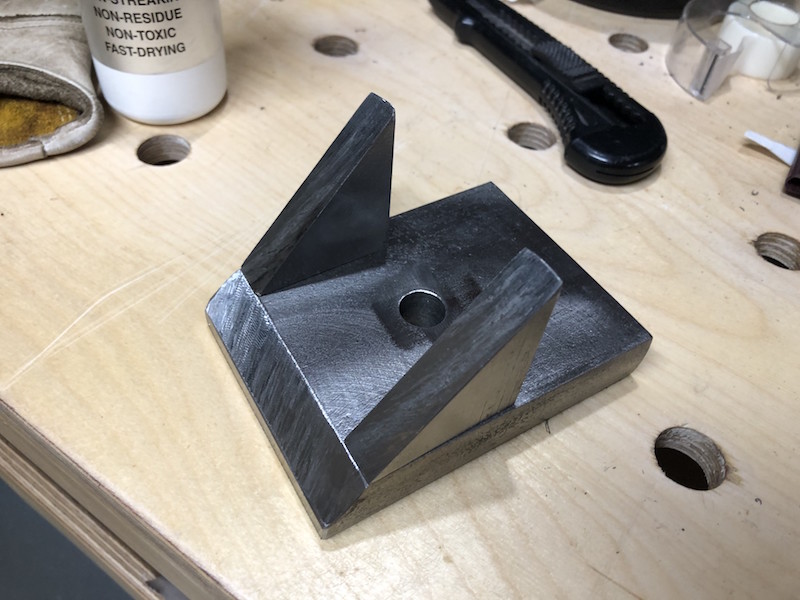
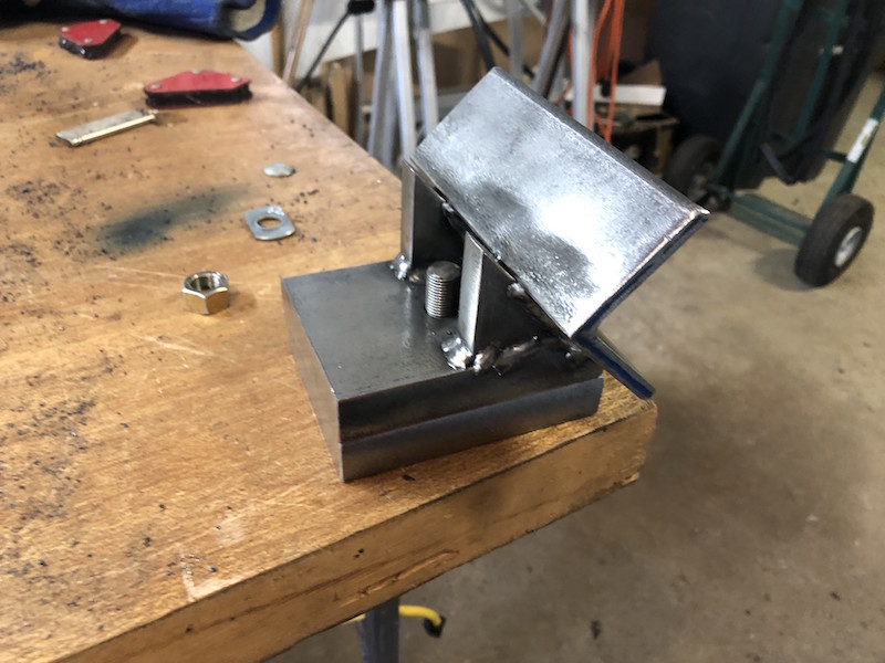
Time to make the upper holder plate. Once again 1/2″ plate is used, the end is beveled to 45 degrees and extended with a triangular piece of plate on each side. A length of heavy angle iron is attached to the triangles and base. The angle iron is horizontal with the center line of the angle at the same height as the center line of the lathe chuck. A 1/2″ stud is attached to the bottom plate and passes through the upper holder allowing it to rotate and be locked down at any angle.
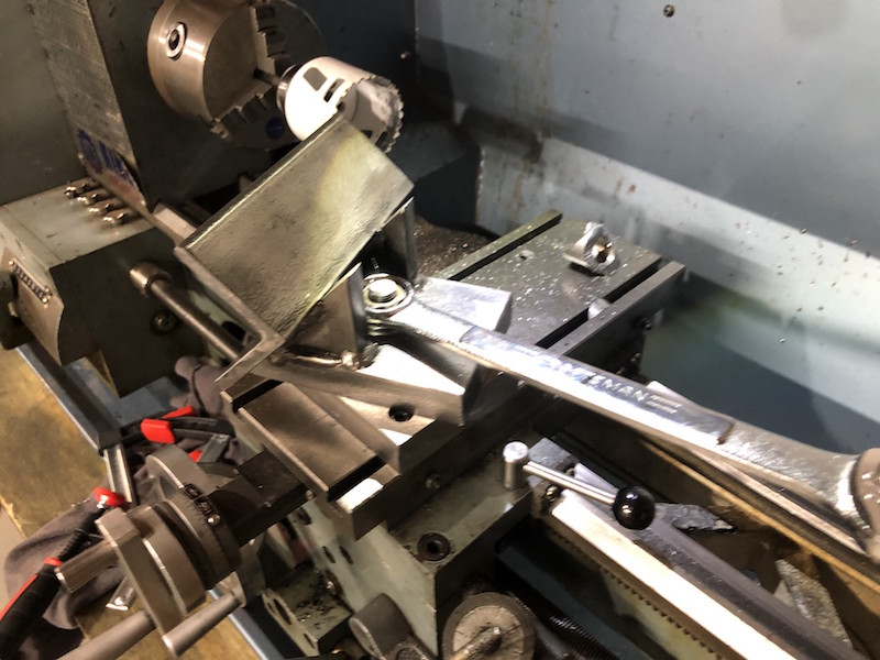
With the basic parts finished it’s time to test. The holder is mounted on the cross slide and the desired angle is set and locked. A hole saw of appropriate diameter is mounted in the lathe chuck and a piece of tubing is clamped in the holder. I use the lathe travel to manually feed the tubing into the hole saw and make the cut.
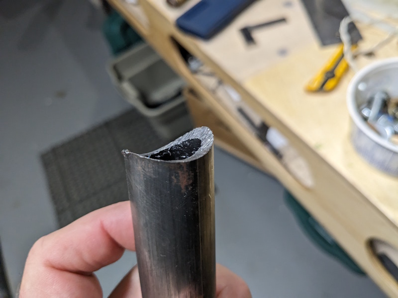
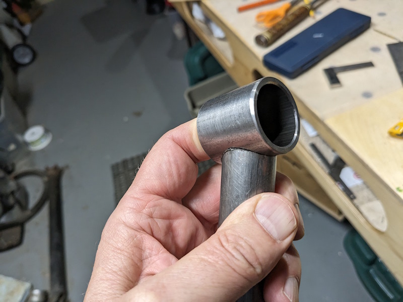
The end result is a very tight fit between the tubes.
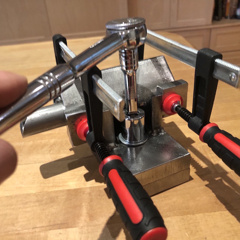
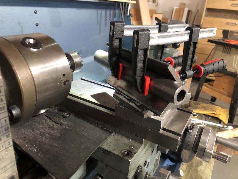
Here are the completed components, clamping tabs were added to the top plate, a front clamping bar was made to make attaching round tube more secure and enough relief was created to allow a ratchet to be used for angle locking. This geometry means that any diameter of tube clamped in the holder will be centered on the hole saw without any adjustment needed.
![]()